element14 Community
element14 Community
    Register Log In
  • Site
  • Search
  • Log In Register
  • About Us
  • Community Hub
    Community Hub
    • What's New on element14
    • Feedback and Support
    • Benefits of Membership
    • Personal Blogs
    • Members Area
    • Achievement Levels
  • Learn
    Learn
    • Ask an Expert
    • eBooks
    • element14 presents
    • Learning Center
    • Tech Spotlight
    • STEM Academy
    • Webinars, Training and Events
    • Learning Groups
  • Technologies
    Technologies
    • 3D Printing
    • FPGA
    • Industrial Automation
    • Internet of Things
    • Power & Energy
    • Sensors
    • Technology Groups
  • Challenges & Projects
    Challenges & Projects
    • Design Challenges
    • element14 presents Projects
    • Project14
    • Arduino Projects
    • Raspberry Pi Projects
    • Project Groups
  • Products
    Products
    • Arduino
    • Avnet Boards Community
    • Dev Tools
    • Manufacturers
    • Multicomp Pro
    • Product Groups
    • Raspberry Pi
    • RoadTests & Reviews
  • Store
    Store
    • Visit Your Store
    • Choose another store...
      • Europe
      •  Austria (German)
      •  Belgium (Dutch, French)
      •  Bulgaria (Bulgarian)
      •  Czech Republic (Czech)
      •  Denmark (Danish)
      •  Estonia (Estonian)
      •  Finland (Finnish)
      •  France (French)
      •  Germany (German)
      •  Hungary (Hungarian)
      •  Ireland
      •  Israel
      •  Italy (Italian)
      •  Latvia (Latvian)
      •  
      •  Lithuania (Lithuanian)
      •  Netherlands (Dutch)
      •  Norway (Norwegian)
      •  Poland (Polish)
      •  Portugal (Portuguese)
      •  Romania (Romanian)
      •  Russia (Russian)
      •  Slovakia (Slovak)
      •  Slovenia (Slovenian)
      •  Spain (Spanish)
      •  Sweden (Swedish)
      •  Switzerland(German, French)
      •  Turkey (Turkish)
      •  United Kingdom
      • Asia Pacific
      •  Australia
      •  China
      •  Hong Kong
      •  India
      •  Korea (Korean)
      •  Malaysia
      •  New Zealand
      •  Philippines
      •  Singapore
      •  Taiwan
      •  Thailand (Thai)
      • Americas
      •  Brazil (Portuguese)
      •  Canada
      •  Mexico (Spanish)
      •  United States
      Can't find the country/region you're looking for? Visit our export site or find a local distributor.
  • Translate
  • Profile
  • Settings
Arduino
  • Products
  • More
Arduino
Arduino Forum ULN2003A driving IRF540N mosfet
  • Blog
  • Forum
  • Documents
  • Quiz
  • Events
  • Polls
  • Files
  • Members
  • Mentions
  • Sub-Groups
  • Tags
  • More
  • Cancel
  • New
Join Arduino to participate - click to join for free!
Actions
  • Share
  • More
  • Cancel
Forum Thread Details
  • State Suggested Answer
  • Replies 34 replies
  • Answers 1 answer
  • Subscribers 395 subscribers
  • Views 6252 views
  • Users 0 members are here
Related

ULN2003A driving IRF540N mosfet

wallarug
wallarug over 10 years ago

Hey guys,


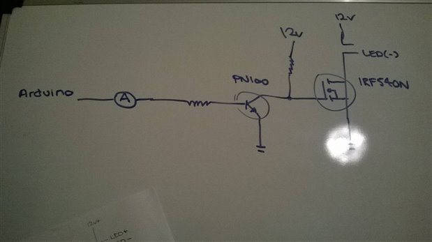
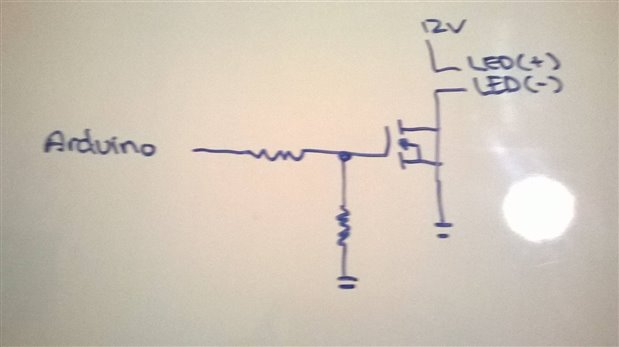
I am trying to expand the number of outputs on a board that I built 6 months ago that controls high current LED strips but am unsure if the following would work. Could someone please let me know if what I am trying to do in the following schematic will even work??


Thanks is advance.


imageimage


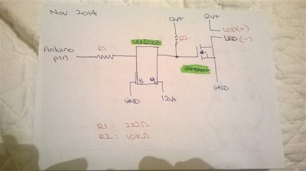
PS: I am aware of the 'negative logic' on the march 2014 version.

  • Sign in to reply
  • Cancel
Parents
  • michaelkellett
    0 michaelkellett over 10 years ago

    It should work but with a warning: - if you check out the data sheet for the ULN2003 (I looked at the TI data sheet) you'll see that even with very low load current the output voltage doesn't drop below 0.7V.


    If you use an IRF540N from IR you should be OK - the gate threshold voltage is 2V worst case for 250uA drain current.

    If you use a MOSFET with a lower threshold voltage it may not turn off properly.


    You could use an SN7406 which is  a TTL hex inverter with OC outputs, capable of withstanding 30V on the OC outputs.

    Be careful is you go this route because other logic families offer similar parts but not all will take the 30V on the output.


    MK

    • Cancel
    • Vote Up 0 Vote Down
    • Sign in to reply
    • Verify Answer
    • Cancel
  • wallarug
    0 wallarug over 10 years ago in reply to michaelkellett
    It should work but with a warning: - if you check out the data sheet for the ULN2003 (I looked at the TI data sheet) you'll see that even with very low load current the output voltage doesn't drop below 0.7V.

    Could you please explain this further?  What do you mean by: "[even with] low load current, the output voltage doesn't drop below 0.7V".  Does this mean that when the ULN2003 is in an OFF state that there will still be voltage supplied to the MOSFET?


    Does that still apply if I am using 5v input with 12v output?


    Otherwise, thank you for the fast reply.

    • Cancel
    • Vote Up 0 Vote Down
    • Sign in to reply
    • Verify Answer
    • Cancel
  • Robert Peter Oakes
    0 Robert Peter Oakes over 10 years ago in reply to wallarug

    The ULN2003 is not providing a voltage to the mosfet, it is an open collector device (Meaning it can ONLY sink current, not source it) and will only be able to sink the voltage provided to the mosfet through the resistor (R2 in your diagrams above), when the ULN2003 output is turned on fully it will try to take its output to ground but because of the characteristics of a transistor, the Collector to Emitter voltage will never go below 700mV even with a low current which is the case here.


    see this excerpt from the data sheet

    image

    Look at the Vce(sat) for what were talking about


    If you want a device compatable with the ULN2003 but with better Vce then go for the FET version from TI, the "TPIC2701 7-CHANNEL COMMON-SOURCE POWER DMOS ARRAY"

    its on voltage is significantly lower and it is basically the same device to you

    Data sheet here http://www.ti.com/lit/ds/slis019a/slis019a.pdf


    in the diagram below the equivalent parameter is the Vds(on)

    image

    So its not that the device is preventing the gate voltage to the MOSFET going high enough, it is just there's a risk it cant pull it low enough to turn off the MOSFET completely as the MOSFET Vgs(threshold) is typically 2 - 4V. It should be ok, but there is not much room for error with the ULN2003, the 2701 on the other hand is way better

    Here is the snipet from the mosfet datasheet, look at the Vgs(th)

    image

    Hope this helps

    • Cancel
    • Vote Up 0 Vote Down
    • Sign in to reply
    • Verify Answer
    • Reject Answer
    • Cancel
  • wallarug
    0 wallarug over 10 years ago in reply to Robert Peter Oakes
    The ULN2003 is not providing a voltage to the mosfet, it is an open collector device (Meaning it can ONLY sink current, not source it) and will only be able to sink the voltage provided to the mosfet through the resistor (R2 in your diagrams above)

    I understand. 


    when the ULN2003 output is turned on fully it will try to take its output to ground but because of the characteristics of a transistor, the Collector to Emitter voltage will never go below 700mV even with a low current which is the case here.

    I see... so when the transistor is 'on' it still has to use 0.7v - 1.2v which then flows through the Collector-Emitter circuit, into the MOSFET in this case.  Since the MOSFET has a threshold voltage of 2v, it won't turn on, so it is not a problem...

    So its not that the device is preventing the gate voltage to the MOSFET going high enough, it is just there's a risk it cant pull it low enough to turn off the MOSFET completely as the MOSFET Vgs(threshold) is typically 2 - 4V. It should be ok,


    I think I understand all of this now.  Thank you very much Robert Peter Oakes .


    If I was to just skip the ULN2003 and control the IRF540N MOSFET directly with a Arduino or RPi:

    Q1. What would be the current used in the gate of the IRF540N from a 3v3 supply (yes... I know that this risks the threshold voltage not being reached) with a load of 12v @ 3 Amps?


    I measured the input current on the already built board that used the PN100 transistor as a control for the IRF540N at 3.65mA (@3v3 volts) which is higher than what I wanted. I was hoping to get the base/gate current down to about 1.3mA (@3v3 volts).

    • Cancel
    • Vote Up 0 Vote Down
    • Sign in to reply
    • Verify Answer
    • Cancel
  • Robert Peter Oakes
    0 Robert Peter Oakes over 10 years ago in reply to wallarug

    image, that's the fun question


    The Gate once turned on has NO (0mA) current, think of it as a capacitor to ground, so it has an inrush as the cap charges up, once charged there is no current, limit the current inrush with a 1 - 10K resistor and it should work just fine, don't switch too fast (Keep under a few hundred Hz) as the resistor will slow down the switch on but improve the stability and minimize ringing in the output, if you try to switch too fast the FET will start to remain in its linear region and heat up as it is never fully off or fully on (The RC constant of the gate resistor and the gate capacitance)


    The current your seeing is probably the pull up resistor and the draw on the driver transistors

    • Cancel
    • Vote Up 0 Vote Down
    • Sign in to reply
    • Verify Answer
    • Cancel
  • wallarug
    0 wallarug over 10 years ago in reply to Robert Peter Oakes

    Learning is fun!


    Just going back to the current I measured.  Here is a schematic of what I did (with Multimeter in place):

    image

    image

    image

    Values: 

    ~3.5mA when Arduino sent 5v into PN100

    0mA when Arduino sent 0v into PN100


    Hopefully I am reading the multimeter correctly.


    The current your seeing is probably the pull up resistor and the draw on the driver transistors

    That's what I thought! image


    The Gate once turned on has NO (0mA) current, think of it as a capacitor to ground, so it has an inrush as the cap charges up, once charged there is no current, limit the current inrush with a 1 - 10K resistor and it should work just fine, don't switch too fast (Keep under a few hundred Hz) as the resistor will slow down the switch on but improve the stability and minimize ringing in the output, if you try to switch too fast the FET will start to remain in its linear region and heat up as it is never fully off or fully on (The RC constant of the gate resistor and the gate capacitance)

    That all makes perfect sense! So it will be 'safe' to drive the MOSFETs directly from a microcontroller (Raspberry Pi) with a 1k-10k gate resistor ( I worked out that 2k2 might be the magic number there image).

    image


    I planned to continue using my Raspberry Pi to switch them on, off and PWM them.  This should be ok since the raspberry pi's PWM is at a maximum of 100Hz.  Each GPIO pin can handle 1.5mA each (50mA/26 pins = ~1.9mA) which a 2k2 Ohm resistor will help limit the current to 1.5mA.  Pull-down resistor included for good practice (10k).


    If anything above is incorrect please let me know.


    Thanks again!!

    • Cancel
    • Vote Up 0 Vote Down
    • Sign in to reply
    • Verify Answer
    • Cancel
  • mcb1
    0 mcb1 over 10 years ago in reply to wallarug

    Wallarug


    Your theory is right BUT there is no such thing as bullet proof and if the FET goes faulty it can dump the 12v up the GPIO.

    I'd advise using optocouplers to isolate the RPi GPIO from any possble damage.


    The FET is a voltage controlled device while the transistor is a current controlled device.

    For your current measuring, you probably should measure the voltage across the Collector Emitter junction to ensure the switching is rail to rail (ie zero to 12v)


    Mark

    • Cancel
    • Vote Up 0 Vote Down
    • Sign in to reply
    • Verify Answer
    • Cancel
  • gdstew
    0 gdstew over 10 years ago in reply to wallarug

    A series current limiting resistor is not needed for a MOSFET. The gate of the MOSFET is primarily a capacitive load with high input impedance and almost no current (there is some leakage in the gate "capacitor))

    required to maintain it in the on state. This means it is a voltage (not current) controlled device. Normally a series resistor between 4.K and 10K is used to help better match the output impedance of the driver to the

    input impedance of the MOSFET. At 100 KHz you may want to stay near the lower values to improve off to on switching times (some current is needed to charge the gate capacitor when switching).


    While you can use an opto-isolator to isolate the Raspberry Pi output from the voltage the MOSFET is driving the gate of the MOSFET is electrically isolated from the source and drain by a insulator between the

    gate and the source/drain conduction channel it is controlling. This provides some level of protection as long as the gate insulator breakdown voltage between the gate and the conduction channel is not exceeded.

    So in your case (a primarily non-inductive load) with a properly selected MOSFET an opto-isolator is overkill unless you want to be really, really, really safe. It would be even better if the source of the 12V has over

    voltage shutdown protection which many (but not all) voltage regulators do.

    • Cancel
    • Vote Up 0 Vote Down
    • Sign in to reply
    • Verify Answer
    • Cancel
  • Robert Peter Oakes
    0 Robert Peter Oakes over 10 years ago in reply to gdstew

    The series resistor also provides slew rate limiting and will prevent or at least limit the output of the MOSFET from ringing, this can be substantial without the resistor and I have seen this first hand where it would drive my Keithley power supply crazy as it oscillated through capacitive feedback between gate, Drain and Source. Yes in some cases you can get away without the resistor but ultimately not worth the effort of not having it

    • Cancel
    • Vote Up 0 Vote Down
    • Sign in to reply
    • Verify Answer
    • Cancel
  • michaelkellett
    0 michaelkellett over 10 years ago in reply to Robert Peter Oakes

    If the MOSFET is only switching relatively low voltages (less than 60V)  an opto isolator is quite un-necessary.  The 10k series resistor is a good idea because although it will slow the MOSFET down a lot it will also protect the micro-controller from power fed back from a failed MOSFET.

    If the MOSFET is driven directly by the Arduino you must pick one which will turn on properly with only 5V gate voltage. I wouldn't use the IRF540N because (at least in the IR data sheet) the on resistance is not specified for 5V gate drive.

    Using a photo darlington type opto isolator would mean the you must pick a MOSFET with a high gate threshold voltage.

    Remember when choosing parts that you can't count on anything that isn't specified.


    The TPIC2701 device suggested is nice but obsolete - you can't buy them from Farnell, RS, DigiKey or Mouser so it's best avoided.


    To summarise, if you don't wont to go fast use the Arduino driving a suitable MOSFET (logic level threshold) though a resistor (10k is good value for slow switching).

    If you need to go fast use a driver, either  a proper MOSFET driver for really fast, or an open collector device like the 7406 or an opto-isolator (but don't use a darlington type - and drive it as hard as you can within the limitations of the Arduino's outputs.)


    MK

    • Cancel
    • Vote Up 0 Vote Down
    • Sign in to reply
    • Verify Answer
    • Cancel
Reply
  • michaelkellett
    0 michaelkellett over 10 years ago in reply to Robert Peter Oakes

    If the MOSFET is only switching relatively low voltages (less than 60V)  an opto isolator is quite un-necessary.  The 10k series resistor is a good idea because although it will slow the MOSFET down a lot it will also protect the micro-controller from power fed back from a failed MOSFET.

    If the MOSFET is driven directly by the Arduino you must pick one which will turn on properly with only 5V gate voltage. I wouldn't use the IRF540N because (at least in the IR data sheet) the on resistance is not specified for 5V gate drive.

    Using a photo darlington type opto isolator would mean the you must pick a MOSFET with a high gate threshold voltage.

    Remember when choosing parts that you can't count on anything that isn't specified.


    The TPIC2701 device suggested is nice but obsolete - you can't buy them from Farnell, RS, DigiKey or Mouser so it's best avoided.


    To summarise, if you don't wont to go fast use the Arduino driving a suitable MOSFET (logic level threshold) though a resistor (10k is good value for slow switching).

    If you need to go fast use a driver, either  a proper MOSFET driver for really fast, or an open collector device like the 7406 or an opto-isolator (but don't use a darlington type - and drive it as hard as you can within the limitations of the Arduino's outputs.)


    MK

    • Cancel
    • Vote Up 0 Vote Down
    • Sign in to reply
    • Verify Answer
    • Cancel
Children
  • mcb1
    0 mcb1 over 10 years ago in reply to michaelkellett

    Michael

    If you were to read all the reasons the opto-coupler was suggested, it wasn't just for protection.

    Yes if nothing ever goes wrong, then nothing should ever destroy the controller ... never seen that "nothing ever breaks scenario" in my career, but it's possible.


    Wallarugs last project included the abilty to PWM, and I'm assumming that the design should allow for it in this one.

    He hasn't said it will or won't so we are tending to allow for it.


    Some of the parts were choosen due to local suppliers and availability, so while you are correct and there may be other choices, we work with what the OP has suggested.


    I think Wallarug learned an awful lot in the last round (along with some other observers), and it's great that he is prepared to engage and increase his knowledge.


    Mark

    • Cancel
    • Vote Up 0 Vote Down
    • Sign in to reply
    • Verify Answer
    • Cancel
  • michaelkellett
    0 michaelkellett over 10 years ago in reply to mcb1

    I'm not quite sure what you are getting at here:

    If you need to pwm the speed of the opto-isolator must be considered - the single transistor types mentioned in previous posts in this thread have turn off times of the order of 20uS and the darlington more like 40uS (both could be a lot worse but won't get much better as you change drive levels and loads). 20us turn off time would, in my book, suggest a maximum  switching frequency of 5kHz but for good efficiency below 500Hz. That's OK for some stuff but not very fast.


    Of course there are fast opto-couplers and isolating devices but they are expensive and actually don't usually have the ability to drive  MOSFETs directly.


    If you need protection and don't need speed (and I suggested only good up to about 60V) then a 10k resistor is fine. If you check on the ATmega328 data sheet it shows that all the IO is protected by diodes to OV and supply but I couldn't find a maximum current spec for them. The 60V and 10k combination results in only 6mA of fault current which is (based on other device specs) very unlikely to damage the processor.


    MK

    • Cancel
    • Vote Up 0 Vote Down
    • Sign in to reply
    • Verify Answer
    • Cancel
  • mcb1
    0 mcb1 over 10 years ago in reply to michaelkellett

    MK

    You may have missed this in reply #7

    I planned to continue using my Raspberry Pi to switch them on, off and PWM them.  This should be ok since the raspberry pi's PWM is at a maximum of 100Hz.  Each GPIO pin can handle 1.5mA each (50mA/26 pins = ~1.9mA) which a 2k2 Ohm resistor will help limit the current to 1.5mA.  Pull-down resistor included for good practice (10k).


    One of the other 'adantages' of using the opto-coupler was to make the board versatile and able to be located some distance away from the controller.


    Perhaps this blog has shown that we should have something that covers driving large loads and some sensible and relatively cheap options.

    Pity the site doesnt allow those 'sticky' posts so everyone can easily find it.


    Mark

    • Cancel
    • Vote Up 0 Vote Down
    • Sign in to reply
    • Verify Answer
    • Cancel
element14 Community

element14 is the first online community specifically for engineers. Connect with your peers and get expert answers to your questions.

  • Members
  • Learn
  • Technologies
  • Challenges & Projects
  • Products
  • Store
  • About Us
  • Feedback & Support
  • FAQs
  • Terms of Use
  • Privacy Policy
  • Legal and Copyright Notices
  • Sitemap
  • Cookies

An Avnet Company © 2025 Premier Farnell Limited. All Rights Reserved.

Premier Farnell Ltd, registered in England and Wales (no 00876412), registered office: Farnell House, Forge Lane, Leeds LS12 2NE.

ICP 备案号 10220084.

Follow element14

  • X
  • Facebook
  • linkedin
  • YouTube