In my current project I'm using 2 Arduinos and wan't them to communicate via an ethernet cable.
All that works, and they are communicating through a 30meter cable just fine, Now my next step is to power one of the arduinos through the same cable.
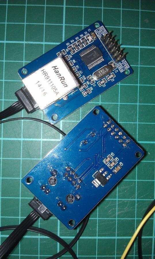
and for that I have these spare ethernet port modules laying around.
My plan is to simply unsolder the resistors on both modules and attach a set of wires instead.
Ofcourse only for the 2 wires needed.
I find it to be a better solution than to unisolate the wire and pull out the wires from the main cable.
BTW. the cable on the picture is not the Actual cable, that is just a test cable.
my question is now,
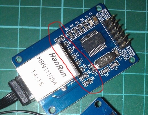
Which of the resistors would you think would be "FREE" I was thinking the blue or brown/red set since they are not
used, but to which resistors are they allocated on this module?
Or same question rephrased,
To which of the topside resistors are cables 4,5 (blue) and 7,8 (red) connected to ?
P.s we can talk about how much voltage actual required to be send down the line later to achieve the 5-7 volts needed.