element14 Community
element14 Community
    Register Log In
  • Site
  • Search
  • Log In Register
  • About Us
  • Community Hub
    Community Hub
    • What's New on element14
    • Feedback and Support
    • Benefits of Membership
    • Personal Blogs
    • Members Area
    • Achievement Levels
  • Learn
    Learn
    • Ask an Expert
    • eBooks
    • element14 presents
    • Learning Center
    • Tech Spotlight
    • STEM Academy
    • Webinars, Training and Events
    • Learning Groups
  • Technologies
    Technologies
    • 3D Printing
    • FPGA
    • Industrial Automation
    • Internet of Things
    • Power & Energy
    • Sensors
    • Technology Groups
  • Challenges & Projects
    Challenges & Projects
    • Design Challenges
    • element14 presents Projects
    • Project14
    • Arduino Projects
    • Raspberry Pi Projects
    • Project Groups
  • Products
    Products
    • Arduino
    • Avnet Boards Community
    • Dev Tools
    • Manufacturers
    • Multicomp Pro
    • Product Groups
    • Raspberry Pi
    • RoadTests & Reviews
  • Store
    Store
    • Visit Your Store
    • Choose another store...
      • Europe
      •  Austria (German)
      •  Belgium (Dutch, French)
      •  Bulgaria (Bulgarian)
      •  Czech Republic (Czech)
      •  Denmark (Danish)
      •  Estonia (Estonian)
      •  Finland (Finnish)
      •  France (French)
      •  Germany (German)
      •  Hungary (Hungarian)
      •  Ireland
      •  Israel
      •  Italy (Italian)
      •  Latvia (Latvian)
      •  
      •  Lithuania (Lithuanian)
      •  Netherlands (Dutch)
      •  Norway (Norwegian)
      •  Poland (Polish)
      •  Portugal (Portuguese)
      •  Romania (Romanian)
      •  Russia (Russian)
      •  Slovakia (Slovak)
      •  Slovenia (Slovenian)
      •  Spain (Spanish)
      •  Sweden (Swedish)
      •  Switzerland(German, French)
      •  Turkey (Turkish)
      •  United Kingdom
      • Asia Pacific
      •  Australia
      •  China
      •  Hong Kong
      •  India
      •  Korea (Korean)
      •  Malaysia
      •  New Zealand
      •  Philippines
      •  Singapore
      •  Taiwan
      •  Thailand (Thai)
      • Americas
      •  Brazil (Portuguese)
      •  Canada
      •  Mexico (Spanish)
      •  United States
      Can't find the country/region you're looking for? Visit our export site or find a local distributor.
  • Translate
  • Profile
  • Settings
Arduino
  • Products
  • More
Arduino
Arduino Forum Atmega328P-PU (arduino uno) from breadboard to pcb
  • Blog
  • Forum
  • Documents
  • Quiz
  • Events
  • Polls
  • Files
  • Members
  • Mentions
  • Sub-Groups
  • Tags
  • More
  • Cancel
  • New
Join Arduino to participate - click to join for free!
Actions
  • Share
  • More
  • Cancel
Forum Thread Details
  • State Not Answered
  • Replies 22 replies
  • Subscribers 397 subscribers
  • Views 1877 views
  • Users 0 members are here
  • atmega328
  • arduino
Related

Atmega328P-PU (arduino uno) from breadboard to pcb

bobj6
bobj6 over 10 years ago

Hello everybody.


I been working with an arduino uno for a few years now and i decide to make them standalone.

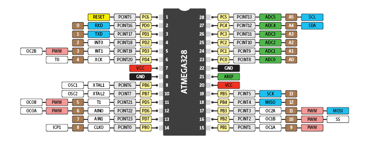
So i bought some Atmega328P-PU and start putting them on a breadboard with a Crystal and a few capacitors

I have loaded the BLINK example onto my Atmega chip and this works fine, The led blinks with an interval of aproximilly a 1/2 second.


Now this works i have solderd one onto a PCB.

I used a Voltage regulator (L7805ABV) to make 5 volts out of 12 volts.

the Atmega does get power and ground and the Crystal is also correct installed.

But when i start it up the led on pin 13 doesn't light up.

When I touch the plastic of the Atmega chip the led does ligt up, But flashes way to fast (Not the 1/2 a second it should).


does anyone have an idea what is going wrong here?

I thank you in advance.


Yours sincerly,

Bob

  • Sign in to reply
  • Cancel

Top Replies

  • shabaz
    shabaz over 10 years ago +3
    It sounds like a couple of things; probably a floating reset pin (that would explain why a finger near it makes a difference) and also probably the config reg fuse values have an incorrect prescaler value…
  • bobj6
    bobj6 over 10 years ago in reply to clem57 +2
    I am using ic sockets so i dont solder with the chip on the board.
  • kidiccurus
    kidiccurus over 10 years ago +2
    I have been doing this recently and have had an issue with a dead crystal after a short. The chip didn't work at all in my board but was fine in the original arduino. I'm waiting for some replacements…
Parents
  • Robert Peter Oakes
    0 Robert Peter Oakes over 10 years ago

    The reset line needs more than just a 10K pull up, it also needs a 100nF to ground to form an RC circuit

    see the official schematics where it is clearly shown

    http://www.arduino.cc/en/uploads/Main/Arduino_Uno_Rev3-schematic.pdf

    • Cancel
    • Vote Up 0 Vote Down
    • Sign in to reply
    • Verify Answer
    • Cancel
  • mcb1
    0 mcb1 over 10 years ago in reply to Robert Peter Oakes

    They seem to ignore that on the breadboard version.

    http://www.arduino.cc/en/Main/Standalone


    I suspect its actually for debouncing the switch.

    I'd be adding it anyway.


    mark

    • Cancel
    • Vote Up 0 Vote Down
    • Sign in to reply
    • Verify Answer
    • Cancel
  • bobj6
    0 bobj6 over 10 years ago in reply to mcb1

    I dont think it has anything to do with the reset switch.

    since it works fine on my breadboard.


    what i do realish just now is that i dont have any capacitors over the voltage regulator.

    on my breadboard i am using a 5 volts pc supply so i dont use a regulator on my breadboard.

    it might be possible that i have noise on the pcb version.


    I do have the 2 capacitors from the crystal to ground.

    where does the 10uf capacitor go. (or is this for the regulator in that case i dont have one at the moment)

    • Cancel
    • Vote Up 0 Vote Down
    • Sign in to reply
    • Verify Answer
    • Cancel
  • Robert Peter Oakes
    0 Robert Peter Oakes over 10 years ago in reply to bobj6

    you should always have some de-coupling capacitors close to the 328 across the supply, from AVcc to gnd and Vcc to gnd, about 100nF (0.1uF) would suffice for that, and a bigger 10 - 100uF across the supply too on the board (Yes a 10uF in parallel with 0.1uF, it is not for the combined smoothing but the way capacitors internal composition react to different frequencies. the larger capacitor takes care of local smoothing and the smaller ones take care of higher frequency switching noise etc that the larger one will not adequatly handle.

    • Cancel
    • Vote Up 0 Vote Down
    • Sign in to reply
    • Verify Answer
    • Cancel
  • Robert Peter Oakes
    0 Robert Peter Oakes over 10 years ago in reply to bobj6

    breadboards also have quite a capacitance between the metal strips that can either hide issues or create them and you always need to be aware of this. A breadboard is a great way to prototype solutions but when the system is running at 16Mhz these stray capacitances and Inductance starts to have an affect. so not having a capacitor on the reset to ground can work on a breadboard but may fail on a real pcb as the conditions are very different


    I am not saing that the capacitor is absolutly necessary but as mcb1 says, it can provide de-bouncing of a reset switch and in addition it also provides for an additional delay while the power supplies stabilize etc.


    My main point here is that, just because something works (Or does not work) on a bread board does not mean the same will be true for when it is transfered to a PCB. for slower analogue systems it is more lightly to work but at higher frequencies or faster pulses things are very different

    • Cancel
    • Vote Up +1 Vote Down
    • Sign in to reply
    • Verify Answer
    • Cancel
Reply
  • Robert Peter Oakes
    0 Robert Peter Oakes over 10 years ago in reply to bobj6

    breadboards also have quite a capacitance between the metal strips that can either hide issues or create them and you always need to be aware of this. A breadboard is a great way to prototype solutions but when the system is running at 16Mhz these stray capacitances and Inductance starts to have an affect. so not having a capacitor on the reset to ground can work on a breadboard but may fail on a real pcb as the conditions are very different


    I am not saing that the capacitor is absolutly necessary but as mcb1 says, it can provide de-bouncing of a reset switch and in addition it also provides for an additional delay while the power supplies stabilize etc.


    My main point here is that, just because something works (Or does not work) on a bread board does not mean the same will be true for when it is transfered to a PCB. for slower analogue systems it is more lightly to work but at higher frequencies or faster pulses things are very different

    • Cancel
    • Vote Up +1 Vote Down
    • Sign in to reply
    • Verify Answer
    • Cancel
Children
  • kidiccurus
    0 kidiccurus over 10 years ago in reply to Robert Peter Oakes

    One other small thing to check, is the chip in the socket the correct way round? I will admit to making this mistake once, and whilst the chip survived, the circuit (obviously) did not work.

    • Cancel
    • Vote Up 0 Vote Down
    • Sign in to reply
    • Verify Answer
    • Cancel
  • mcb1
    0 mcb1 over 10 years ago in reply to kidiccurus

    is the chip in the socket the correct way round

    I struggle to see it working unless AREF got tied to +Vcc  ... but still worth a mention.


    image


    Also worth noting here is that a 328 without an oscillator runs at 8MHz.

    This means it will accept an upload but runs at half the speed.

    Scroll down to Arduino IDE to see the effect.

    http://www.element14.com/community/community/design-challenges/forget-me-not/blog/2014/09/12/forget-me-not-eldermon-hardware-hacking-2


    In this case Bob is having trouble with stray capacitance affecting the chip.

    I think we need some good quality images of the board (top and bottom) along with your schematic, as the crystal ball is a little foggy.


    Mark

    • Cancel
    • Vote Up +1 Vote Down
    • Sign in to reply
    • Verify Answer
    • Cancel
  • kidiccurus
    0 kidiccurus over 10 years ago in reply to kidiccurus

    I fixed the problem with my circuit. The crystal was fine, but the was a break in the found going to the 22pf capacitors, rendering the crystal circuitry non-functional. Try checking that both crystals are properly connected to ground and that no traces have been damaged.

    • Cancel
    • Vote Up 0 Vote Down
    • Sign in to reply
    • Verify Answer
    • Cancel
element14 Community

element14 is the first online community specifically for engineers. Connect with your peers and get expert answers to your questions.

  • Members
  • Learn
  • Technologies
  • Challenges & Projects
  • Products
  • Store
  • About Us
  • Feedback & Support
  • FAQs
  • Terms of Use
  • Privacy Policy
  • Legal and Copyright Notices
  • Sitemap
  • Cookies

An Avnet Company © 2025 Premier Farnell Limited. All Rights Reserved.

Premier Farnell Ltd, registered in England and Wales (no 00876412), registered office: Farnell House, Forge Lane, Leeds LS12 2NE.

ICP 备案号 10220084.

Follow element14

  • X
  • Facebook
  • linkedin
  • YouTube