element14 Community
element14 Community
    Register Log In
  • Site
  • Search
  • Log In Register
  • Community Hub
    Community Hub
    • What's New on element14
    • Feedback and Support
    • Benefits of Membership
    • Personal Blogs
    • Members Area
    • Achievement Levels
  • Learn
    Learn
    • Ask an Expert
    • eBooks
    • element14 presents
    • Learning Center
    • Tech Spotlight
    • STEM Academy
    • Webinars, Training and Events
    • Learning Groups
  • Technologies
    Technologies
    • 3D Printing
    • FPGA
    • Industrial Automation
    • Internet of Things
    • Power & Energy
    • Sensors
    • Technology Groups
  • Challenges & Projects
    Challenges & Projects
    • Design Challenges
    • element14 presents Projects
    • Project14
    • Arduino Projects
    • Raspberry Pi Projects
    • Project Groups
  • Products
    Products
    • Arduino
    • Avnet & Tria Boards Community
    • Dev Tools
    • Manufacturers
    • Multicomp Pro
    • Product Groups
    • Raspberry Pi
    • RoadTests & Reviews
  • About Us
    About the element14 Community
  • Store
    Store
    • Visit Your Store
    • Choose another store...
      • Europe
      •  Austria (German)
      •  Belgium (Dutch, French)
      •  Bulgaria (Bulgarian)
      •  Czech Republic (Czech)
      •  Denmark (Danish)
      •  Estonia (Estonian)
      •  Finland (Finnish)
      •  France (French)
      •  Germany (German)
      •  Hungary (Hungarian)
      •  Ireland
      •  Israel
      •  Italy (Italian)
      •  Latvia (Latvian)
      •  
      •  Lithuania (Lithuanian)
      •  Netherlands (Dutch)
      •  Norway (Norwegian)
      •  Poland (Polish)
      •  Portugal (Portuguese)
      •  Romania (Romanian)
      •  Russia (Russian)
      •  Slovakia (Slovak)
      •  Slovenia (Slovenian)
      •  Spain (Spanish)
      •  Sweden (Swedish)
      •  Switzerland(German, French)
      •  Turkey (Turkish)
      •  United Kingdom
      • Asia Pacific
      •  Australia
      •  China
      •  Hong Kong
      •  India
      •  Japan
      •  Korea (Korean)
      •  Malaysia
      •  New Zealand
      •  Philippines
      •  Singapore
      •  Taiwan
      •  Thailand (Thai)
      •  Vietnam
      • Americas
      •  Brazil (Portuguese)
      •  Canada
      •  Mexico (Spanish)
      •  United States
      Can't find the country/region you're looking for? Visit our export site or find a local distributor.
  • Translate
  • Profile
  • Settings
Arduino
  • Products
  • More
Arduino
Arduino Forum 16 RGB LED's in parallel controlled by atmega328 PWM pins for pc case mod. (Updated)
  • Blog
  • Forum
  • Documents
  • Quiz
  • Events
  • Polls
  • Files
  • Members
  • Mentions
  • Sub-Groups
  • Tags
  • More
  • Cancel
  • New
Join Arduino to participate - click to join for free!
Actions
  • Share
  • More
  • Cancel
Forum Thread Details
  • State Verified Answer
  • Replies 24 replies
  • Answers 2 answers
  • Subscribers 419 subscribers
  • Views 3510 views
  • Users 0 members are here
  • pc
  • case-mod
  • atmega328
  • arduino
  • rgb-led
Related

16 RGB LED's in parallel controlled by atmega328 PWM pins for pc case mod. (Updated)

e14 Contributor
e14 Contributor over 12 years ago

Ok I'll start by saying i'm totally new to electronics, (Java programming is my hobby) I'm also new to this site, (The Ben Heck Show brought me here).

Basically I have a really cool plan for a PC build I just completed, all of the fans have 4 blue LED's. I want to replace those with RGB LED's Allowing me to choose any colour I like to suit my mood.

The controls will be mounted in an empty 5.25" drive bay, And consist of 4 push buttons and an RGB led.

Button 1: Mode (Cycle through pre-set colour cycling modes, and static user defined color)

Button 2: +

Button 3: -

Button 4: Colour Select (R, G, B)

You cycle through the pre-sets with the Mode button pre-set X > pre-set X > user defined

The front panel RGB LED will be off while in pre-set mode, when you reach user-defined mode the led will light fully red indicating that the + and - buttons will affect the Red value of the fan lights

Pressing the Color Select button will cause the front rgb led to change to Blue allowing you to alter the Blue value, a further press changes to green then back to red


I'm also hoping in the future to have control over serial from a program running on the pc I intend to write (using one of those SparkFun USB to serial breakout boards connected to an internal USB header) https://www.sparkfun.com/products/718


The entire lighting system will get its power from a 4 pin molex connector coming from the PC PSU


I mocked up a schematic of the circuit in Fritzing, I'm guessing it will work properly, however I may be totally incorrect and pop something


The Micro-controller used will be an ATMEGA328 with the arduino boot loader mounted in a socket on the PCB

its supply voltage will come from the 12V pin of the Molex through a 7805 Voltage regulator


Was also wondering could I do-away with the voltage regulator and power the chip directly using the 5V pin of the molex?

Fullscreen 5415.contentimage_76492.html Download
<html><head><title>Jive SBS</title></head>
<body><font face="arial,helvetica,sans-serif">
<b>Error</b><br><font size="-1">
An general error occurred while processing your request.
</font></font></body></html>

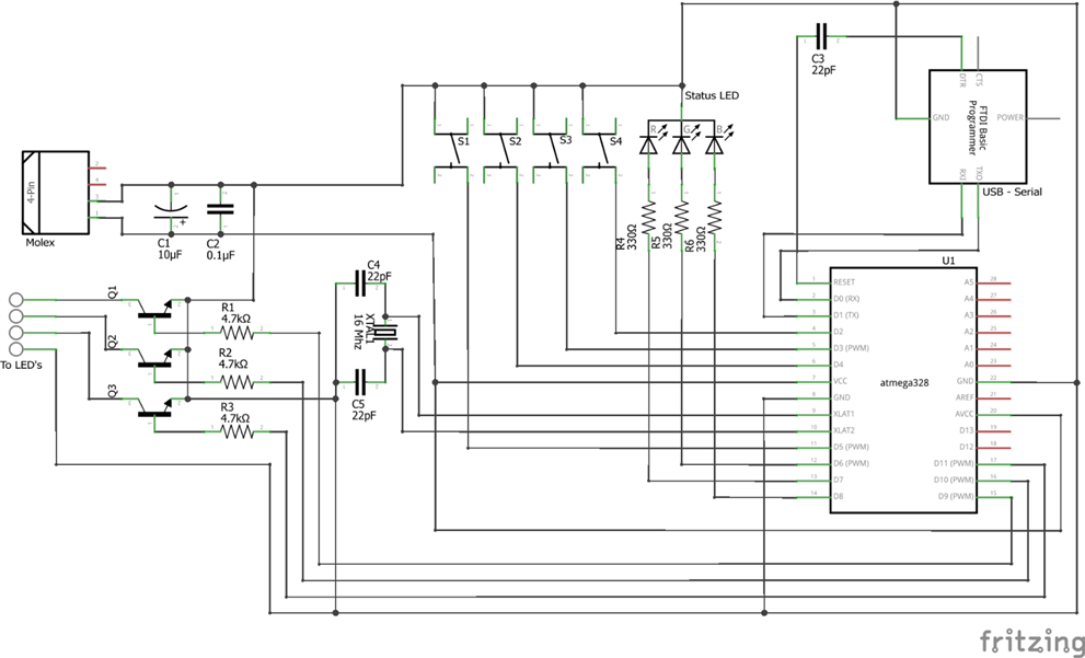
The connector labelled C4 will go to the LED's

The RGB LED's will be Common Anode each colour connected in parallel each with its own current limiting resistor , they will be switched using 3 NPN Transistors one for each colour.

From my calculations based on figures I found on-line each LED colour drawing 20ma * 16 = 320ma per colour channel so my transistors need to be able to switch that load


My main question, Will this work how I have designed it, or will I destroy something? and is there a better way?


Edit:

After doing some research i found using common cathode RGB LED's with PNP transistors wouldn't have worked the way I intended, so i have updated the schematic to reflect this

  • Sign in to reply
  • Cancel

Top Replies

  • mcb1
    mcb1 over 12 years ago in reply to D_Hersey +1
    Don re ATmega 328 as used in this application. Maybe you can code a pull-up in firmware. Thats what the PinMode and DigitalWrite does as stated in Post #2 There is no "Tri State' on a digital output…
Parents
  • e14 Contributor
    0 e14 Contributor over 12 years ago

    Made some changes based on feedback, I still need to correctly calculate the values of R1, R2 and R3

    image

    • Cancel
    • Vote Up 0 Vote Down
    • Sign in to reply
    • Verify Answer
    • Cancel
  • mcb1
    0 mcb1 over 12 years ago in reply to e14 Contributor

    Looking good.


    I'd change the 10uF to 1000uF (or even larger) since the 5v is also supplying your RGB leds which are 320mAx3 (960mA)

    (A rough rule of thumb is 1000uF per Amp)


    For R1-3 you may wish to use a darlington transistor that is capable of 500mA ie MPSA13 or MPSA14 which have a gain of 10-20,000, then you can use a 10k resistor.


    Try to keep your current paths seperate, ie the ground for Q1-3 should go to the supply, the ground for the ATmega 328 should go to the supply and both join at the supply point.

    A bit like keeping heavy traffic from residential streets but joining them at the motorway on-ramp.


    Your FTDI ground should go to the ATmega.

    The idea is to keep any switching currents from influencing the processor.


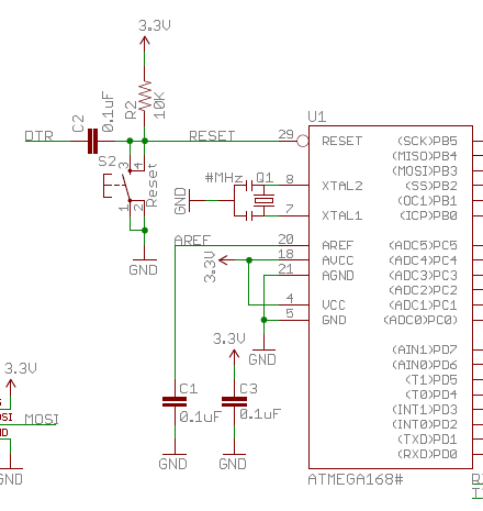
    Most of the ccts I've seen also have a 10k to +5v from the RST pin, and use a 0.1uF to DTR

    Without it it can float, and possibly reset when you don't expect, or not always reset.


    (Arduino Pro shown below)

    image


    Mark

    • Cancel
    • Vote Up 0 Vote Down
    • Sign in to reply
    • Verify Answer
    • Reject Answer
    • Cancel
  • mcb1
    0 mcb1 over 12 years ago in reply to e14 Contributor

    Oops

    I posted and you updated while I was constructing the reply.


    Normally a drawing doesn't match the physical layout, however this is a good exercise to get you thinking about avoiding the pitfalls.

    As you become more familiar with electronics these become second nature ... but they still creep up behind you and slap you if you are sloppy.


    If you build it very similar to your drawing (ie laying it out in the same manner), you should avoid any potential headaches.


    one minor edit ... I'd make the 10k on the reset connect to the ATmega supply line, rather than the 5v to the leds.


    Well done.


    Now the code ....


    Cheers

    mark

    • Cancel
    • Vote Up 0 Vote Down
    • Sign in to reply
    • Reject Answer
    • Cancel
  • mcb1
    0 mcb1 over 12 years ago in reply to mcb1

    sorry I made an edit while you were marking it.

    mark

    • Cancel
    • Vote Up 0 Vote Down
    • Sign in to reply
    • Verify Answer
    • Cancel
  • e14 Contributor
    0 e14 Contributor over 12 years ago in reply to mcb1

    No worries. And thank you for your help, I really do appreciate it.

    I love learning new things. This project is a way for me to learn something new and make something i want in the process, Its actually a good way of learning, your motivation to carry on comes from seeing your idea turn into an actual thing and the satisfaction you get from seeing your creation working at the end of it makes you want to go further, learn more and create more complex things.

    There is probably hundreds of systems pre-built to do what i'm trying to make here, but by building it myself not only do i learn something, but at the end of it i can step back and say "i made that".

    It was the same when i started learning Java, started with a small simple project, and worked my way up from there, did some dabbling with android apps just to learn something else. Wrote tons of programs most of them to serve a purpose, and aid in doing tasks i do regularly, most where a success, a few failed, but the fun is in trying.


    But now down to the code for this, I'm looking forward to this part.

    Also amended my schematic

    Fullscreen 5287.contentimage_182454.html Download
    <html><head><title>Jive SBS</title></head>
    <body><font face="arial,helvetica,sans-serif">
    <b>Error</b><br><font size="-1">
    An general error occurred while processing your request.
    </font></font></body></html>
    

    • Cancel
    • Vote Up 0 Vote Down
    • Sign in to reply
    • Verify Answer
    • Cancel
  • mcb1
    0 mcb1 over 12 years ago in reply to e14 Contributor

    The above attitude to learning will hold you in good stead here .......


    But now down to the code for this, I'm looking forward to this part.

    Plenty of comments so that six months later you (and any others) can understand why you did that bit that way....


    Have a look at the example "Blinkwithoutdelay" in the IDE to use the inbuilt millis() timer, rather than a delay.

    Don't forget to enable the pullups on the three button inputs, and I use a small delay (25mS) then check again to de-bounce the switches.


    Cheers

    Mark

    • Cancel
    • Vote Up 0 Vote Down
    • Sign in to reply
    • Verify Answer
    • Cancel
  • e14 Contributor
    0 e14 Contributor over 12 years ago in reply to mcb1

    Checked out that example, basically the same as System.currentTimeMillis(); I use in some single threaded Java programs that render anything on screen; i.e games, to update something such as a sprite movement at certain intervals without calling Thread.sleep(time); so that the whole program doesn't come to a standstill.

    • Cancel
    • Vote Up 0 Vote Down
    • Sign in to reply
    • Verify Answer
    • Cancel
  • mcb1
    0 mcb1 over 12 years ago in reply to e14 Contributor

    I did think the java experience will show through ....image


    Its very under utilised and doesn't appear in many examples, which is a shame as it catches out quite a few players. (young and old).

    Just rmember to always subtract and you'll avoid the 49.xx day millis() rollover problems (which never shows during testing)


    if you use the EEPROM to store your last settings (for power down), uploading a program doesn't overwrite the EEPROM, which has also caught a few people out.


    Mark

    • Cancel
    • Vote Up 0 Vote Down
    • Sign in to reply
    • Verify Answer
    • Cancel
  • e14 Contributor
    0 e14 Contributor over 12 years ago in reply to mcb1

    Wouldn't using;
    pinMode(#, INPUT_PULLUP);
    do the same as;

    pinMode(#, INPUT);

    digitalWrite(#, HIGH);

    • Cancel
    • Vote Up 0 Vote Down
    • Sign in to reply
    • Verify Answer
    • Cancel
  • mcb1
    0 mcb1 over 12 years ago in reply to e14 Contributor

    Wouldn't using;

    pinMode(#, INPUT_PULLUP);

    Yes


    I didn't run across this til well down the path of Arduino, and haven't seen it the earlier examples.


    Mark

    • Cancel
    • Vote Up 0 Vote Down
    • Sign in to reply
    • Verify Answer
    • Cancel
  • e14 Contributor
    0 e14 Contributor over 12 years ago in reply to mcb1

    Im doing away with the front panel RGB led, now to indicate which color your changing i briefly flash the LED's in the color you'll be altering. now with a simple modification to the code and rearranging a few button inputs, i can free up 3 more PWM pins, my plan is to split the 16 RGB led's (4 per fan) into 2 groups of 8 with the help of another 3 MPSA14's. so that 2 of the LED's per fan can be one color and the other 2 can be a different color allowing me to code some fancy effects. i was wondering what value to use for base resistors on the 6 transistors as all the calculations i have done are suggesting 200k, this to me seems way off the 10k i'm using when driving 16, i have taken into consideration the current for each color channel has dropped from 320ma to 160ma now there are 2 channels for each color

    • Cancel
    • Vote Up 0 Vote Down
    • Sign in to reply
    • Verify Answer
    • Cancel
  • mcb1
    0 mcb1 over 12 years ago in reply to e14 Contributor

    Kawandaio

    Sounds like a good plan.


    The series resistor of 10k is fine.

    While your calculations are fine, the 10k will ensure both the Arduino port and the base of the MPSA14 are within their maximum current limits.

    It will also ensure the base is either ON or Off and not floating due to high impedances.


    I=E/R assumming 1.2v Base to Emitter drop (2x 0.6) and 5v out the Arduino gives 5-1.2 = 3.8v to drop. 3.8/10k = 0.00038 (380uA).

    if the gain is 10,000 then the collector current for saturation (ie fully on) is 0.00038 x 10,000 =  3.8A ie this is well above the 500mA capability.


    The Phillips datasheet I looked at said the B-E current max was 100mA, so you're well within specs.


    Cheers

    Mark

    • Cancel
    • Vote Up 0 Vote Down
    • Sign in to reply
    • Verify Answer
    • Cancel
Reply
  • mcb1
    0 mcb1 over 12 years ago in reply to e14 Contributor

    Kawandaio

    Sounds like a good plan.


    The series resistor of 10k is fine.

    While your calculations are fine, the 10k will ensure both the Arduino port and the base of the MPSA14 are within their maximum current limits.

    It will also ensure the base is either ON or Off and not floating due to high impedances.


    I=E/R assumming 1.2v Base to Emitter drop (2x 0.6) and 5v out the Arduino gives 5-1.2 = 3.8v to drop. 3.8/10k = 0.00038 (380uA).

    if the gain is 10,000 then the collector current for saturation (ie fully on) is 0.00038 x 10,000 =  3.8A ie this is well above the 500mA capability.


    The Phillips datasheet I looked at said the B-E current max was 100mA, so you're well within specs.


    Cheers

    Mark

    • Cancel
    • Vote Up 0 Vote Down
    • Sign in to reply
    • Verify Answer
    • Cancel
Children
No Data
element14 Community

element14 is the first online community specifically for engineers. Connect with your peers and get expert answers to your questions.

  • Members
  • Learn
  • Technologies
  • Challenges & Projects
  • Products
  • Store
  • About Us
  • Feedback & Support
  • FAQs
  • Terms of Use
  • Privacy Policy
  • Legal and Copyright Notices
  • Sitemap
  • Cookies

An Avnet Company © 2026 Premier Farnell Limited. All Rights Reserved.

Premier Farnell Ltd, registered in England and Wales (no 00876412), registered office: Farnell House, Forge Lane, Leeds LS12 2NE.

Follow element14

  • X
  • Facebook
  • linkedin
  • YouTube