element14 Community
element14 Community
    Register Log In
  • Site
  • Search
  • Log In Register
  • About Us
  • Community Hub
    Community Hub
    • What's New on element14
    • Feedback and Support
    • Benefits of Membership
    • Personal Blogs
    • Members Area
    • Achievement Levels
  • Learn
    Learn
    • Ask an Expert
    • eBooks
    • element14 presents
    • Learning Center
    • Tech Spotlight
    • STEM Academy
    • Webinars, Training and Events
    • Learning Groups
  • Technologies
    Technologies
    • 3D Printing
    • FPGA
    • Industrial Automation
    • Internet of Things
    • Power & Energy
    • Sensors
    • Technology Groups
  • Challenges & Projects
    Challenges & Projects
    • Design Challenges
    • element14 presents Projects
    • Project14
    • Arduino Projects
    • Raspberry Pi Projects
    • Project Groups
  • Products
    Products
    • Arduino
    • Avnet Boards Community
    • Dev Tools
    • Manufacturers
    • Multicomp Pro
    • Product Groups
    • Raspberry Pi
    • RoadTests & Reviews
  • Store
    Store
    • Visit Your Store
    • Choose another store...
      • Europe
      •  Austria (German)
      •  Belgium (Dutch, French)
      •  Bulgaria (Bulgarian)
      •  Czech Republic (Czech)
      •  Denmark (Danish)
      •  Estonia (Estonian)
      •  Finland (Finnish)
      •  France (French)
      •  Germany (German)
      •  Hungary (Hungarian)
      •  Ireland
      •  Israel
      •  Italy (Italian)
      •  Latvia (Latvian)
      •  
      •  Lithuania (Lithuanian)
      •  Netherlands (Dutch)
      •  Norway (Norwegian)
      •  Poland (Polish)
      •  Portugal (Portuguese)
      •  Romania (Romanian)
      •  Russia (Russian)
      •  Slovakia (Slovak)
      •  Slovenia (Slovenian)
      •  Spain (Spanish)
      •  Sweden (Swedish)
      •  Switzerland(German, French)
      •  Turkey (Turkish)
      •  United Kingdom
      • Asia Pacific
      •  Australia
      •  China
      •  Hong Kong
      •  India
      •  Korea (Korean)
      •  Malaysia
      •  New Zealand
      •  Philippines
      •  Singapore
      •  Taiwan
      •  Thailand (Thai)
      • Americas
      •  Brazil (Portuguese)
      •  Canada
      •  Mexico (Spanish)
      •  United States
      Can't find the country/region you're looking for? Visit our export site or find a local distributor.
  • Translate
  • Profile
  • Settings
Arduino
  • Products
  • More
Arduino
Arduino Forum ESp32 Interrupt trigger itself issue
  • Blog
  • Forum
  • Documents
  • Quiz
  • Events
  • Polls
  • Files
  • Members
  • Mentions
  • Sub-Groups
  • Tags
  • More
  • Cancel
  • New
Join Arduino to participate - click to join for free!
Actions
  • Share
  • More
  • Cancel
Forum Thread Details
  • Replies 15 replies
  • Subscribers 384 subscribers
  • Views 3768 views
  • Users 0 members are here
  • esp32
  • interrupt
  • pulse
  • reed
  • water measurement
Related

ESp32 Interrupt trigger itself issue

KKaushik
KKaushik over 1 year ago

I need help with an ESP32 project involving a water pulse meter, I've encountered a puzzling issue.

My setup consists of an ESP32 development board connected to a water meter with three pins: Red, Black, and White. I'm utilizing the Red and Black pins, with the Red pin set to PULL-DOWN using a 10K resistor and connected to 3.3V, while the Black pin is grounded.

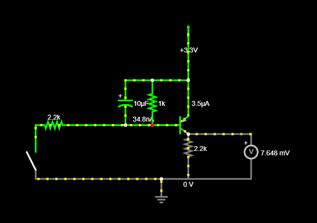
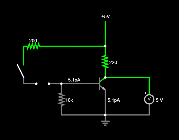
This is the PULL-UP circuit I followed, instead of 5V, its 3.3 V on ESP32
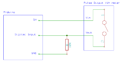
image

Here is code

#include <EEPROM.h>

#define PULSE_ADDRESS 200

#define pin35 35
#define pin25  25
#define pin26  26
#define pin27  27

const int Pulse1 = pin25;
const int Pulse2 = pin26;
const int Pulse3 = pin27;
const int Pulse4 = pin35;


int PulseHit = 1;
const int debounceDelay = 5000;  // Adjust this value based on your requirements

volatile unsigned long lastDebounceTimePulse1 = 0;
volatile unsigned long lastDebounceTimePulse2 = 0;
volatile unsigned long lastDebounceTimePulse3 = 0;
volatile unsigned long lastDebounceTimePulse4 = 0;

volatile unsigned long pulse1Count = 0;
volatile unsigned long pulse2Count = 0;
volatile unsigned long pulse3Count = 0;
volatile unsigned long pulse4Count = 0;

void IRAM_ATTR handlePulse1() {
  
  if ((millis() - lastDebounceTimePulse1) > debounceDelay) {
    PulseHit = 1;
    lastDebounceTimePulse1 = millis();
    pulse1Count++;
  }
}

void IRAM_ATTR handlePulse2() {
  
  if ((millis() - lastDebounceTimePulse2) > debounceDelay) {
    PulseHit = 1;
    lastDebounceTimePulse2 = millis();
    pulse2Count++;
  }
}

void IRAM_ATTR handlePulse3() {
 
  if ((millis() - lastDebounceTimePulse3) > debounceDelay) {
    PulseHit = 1;
    lastDebounceTimePulse3 = millis();

    pulse3Count++;
  }
}

void IRAM_ATTR handlePulse4() {
  
  if ((millis() - lastDebounceTimePulse4) > debounceDelay) {
    PulseHit = 1;
    lastDebounceTimePulse4 = millis();
    pulse4Count++;
  }
}

void setup() {
  Serial.begin(115200);
  pinMode(Pulse1, INPUT);
  pinMode(Pulse2, INPUT);
  pinMode(Pulse3, INPUT);
  pinMode(Pulse4, INPUT);


  attachInterrupt(digitalPinToInterrupt(Pulse1), handlePulse1, RISING);
  attachInterrupt(digitalPinToInterrupt(Pulse2), handlePulse2, RISING);
  attachInterrupt(digitalPinToInterrupt(Pulse3), handlePulse3, RISING);
  attachInterrupt(digitalPinToInterrupt(Pulse4), handlePulse4, RISING);

  lastDebounceTimePulse1 = millis();
  lastDebounceTimePulse2 = millis();
  lastDebounceTimePulse3 = millis();
  lastDebounceTimePulse4 = millis();

  EEPROM.begin(512);
  EEPROM.get(PULSE_ADDRESS, pulse1Count);
  EEPROM.get(PULSE_ADDRESS + sizeof(pulse1Count), pulse2Count);
  EEPROM.get(PULSE_ADDRESS + 2 * sizeof(pulse1Count), pulse3Count);
  EEPROM.get(PULSE_ADDRESS + 3 * sizeof(pulse1Count), pulse4Count);
  EEPROM.end();
}

void loop() {
  // Print the results
  if (PulseHit == 1) {
    Serial.print("RISING Pulse on pin 25: ");
    Serial.println(pulse1Count);

    Serial.print("RISING Pulse on pin 26: ");
    Serial.println(pulse2Count);

    Serial.print("RISING Pulse on pin 27: ");
    Serial.println(pulse3Count);

    Serial.print("RISING Pulse on pin 35: ");
    Serial.println(pulse4Count);

    Serial.println(" ");

    PulseHit = 0;

    // Save pulse counts to EEPROM
    EEPROM.begin(512);
    EEPROM.put(PULSE_ADDRESS, pulse1Count);
    EEPROM.put(PULSE_ADDRESS + sizeof(pulse1Count), pulse2Count);
    EEPROM.put(PULSE_ADDRESS + 2 * sizeof(pulse1Count), pulse3Count);
    EEPROM.put(PULSE_ADDRESS + 3 * sizeof(pulse1Count), pulse4Count);
    EEPROM.commit();
    EEPROM.end();
  }
}


However, I've noticed an unexpected behavior: when I power the ESP32 via an external 5V adapter plugged into a socket, the connected meter wire begins to register signals from the surroundings or some other interference source. Consequently, the pulse counter associated with the GPIO pin (to which the meter's Red-Black wire is connected) starts incrementing

When I power the ESP32 using my laptop, everything functions perfectly fine.
There is no such high signal around the ESP32 either, it just when the powered with socket directly, pulse interrupt doesn't work as required only when power with laptop.

Any suggestion to overcome this self triggering or stop signal interference from external sources.

Things I have tried so far.
Instead of PULL-UP to Red wire and GND to black, I have tried PULL-DOWN to Red wire and 3.3V to Black as well but same response.
I have tried 2596 DC-Dc converter 12v-5v to ESP32, still Same response.
I Have tried lower resistor for PULL-UP 330 ohm, it seem to be working for a while, but when I increased the wire length (Red-black) about 1-2 ft more, it started pulse counter again. 

I can't use the stock? wire of the meter, I need to extend to safe place for ESP32 PCB to install.

  • Sign in to reply
  • Cancel

Top Replies

  • dougw
    dougw over 1 year ago in reply to KKaushik +1
    Filtering is a better way to combat continuous noise, debouncing in software only ignores the noise for the debounce period. You could also try shielding the cable to the switch. If you use a double…
  • shabaz
    shabaz over 1 year ago +1
    Also, have you considered using an optocoupler? You'd use a small series resistor on the LED side, connected to your water meter circuit, ideally with an isolated supply (these are cheap isolated DC…
  • shabaz
    shabaz over 1 year ago in reply to KKaushik +1
    Hi, I think the circuit I sketched should perform much better than the current one, since it has noise filtering, which your circuit doesn't. A difference is the output is inverted in my version, so…
Parents
  • shabaz
    shabaz over 1 year ago

    Also, have you considered using an optocoupler?

    You'd use a small series resistor on the LED side, connected to your water meter circuit, ideally with an isolated supply (these are cheap isolated DC-DC converters, available at very low cost). As a result, the microcontroller side has no long wires to pick up electrical noise, it is right next to the optocoupler.

    Otherwise, at least don't run the microcontroller input directly on long wires, even if you don't use an optocoupler. A BJT at least would be good, with an RC filter on the input. The circuit below could be a possible starting point, for providing at least some noise immunity, including mains hum. There are much better ways but these two options are pretty quick and simple to try out. Also, the two wires to the water meter switch would need to be twin wire or twisted wire.

    image

    • Cancel
    • Vote Up +1 Vote Down
    • Sign in to reply
    • Cancel
  • KKaushik
    KKaushik over 1 year ago in reply to shabaz

    Is there a way to make changes in above circuit for PULL-UP on uC GPIO pin rather than PULL-DOWN?
    As this circuit didn't stop random pulse triggering on GPIO pin.
    image


    So I think if using PULL-UP with 220 ohm (Lower impedance) might help? but not sure what changes to make. Is below circuit is correct?
    image

    • Cancel
    • Vote Up 0 Vote Down
    • Sign in to reply
    • Cancel
  • KKaushik
    KKaushik over 1 year ago in reply to KKaushik

    This is the circuit seems to working great but on a breadboard currently
    image

    image

    If there is anything else I can do to improve  this circuit for long run, please let me know

    • Cancel
    • Vote Up 0 Vote Down
    • Sign in to reply
    • Cancel
  • shabaz
    shabaz over 1 year ago in reply to KKaushik

    Hi,

    I think the circuit I sketched should perform much better than the current one, since it has noise filtering, which your circuit doesn't. A difference is the output is inverted in my version, so I suspect you have a software issue that may have presented itself. If you just want the logic back to what it originally was, so that your code can stay as it is now and you can compare circuits, then you could have added an NPN transistor to the earlier circuit, as shown here:

    image

    I think this is a better basis than the circuit you currently have. If you are still seeing issues, then the filter components could be tweaked, but at least it has that capability compared to the current circuit. And if that is still not reliable (it's only a basic circuit, there's not much hysteresis, nor isolation), you should then strongly consider using an optocoupler. Also, if the ESP32 allows for inputs to be schmitt trigger inpuits, then they should be used.

    • Cancel
    • Vote Up +1 Vote Down
    • Sign in to reply
    • Cancel
Reply
  • shabaz
    shabaz over 1 year ago in reply to KKaushik

    Hi,

    I think the circuit I sketched should perform much better than the current one, since it has noise filtering, which your circuit doesn't. A difference is the output is inverted in my version, so I suspect you have a software issue that may have presented itself. If you just want the logic back to what it originally was, so that your code can stay as it is now and you can compare circuits, then you could have added an NPN transistor to the earlier circuit, as shown here:

    image

    I think this is a better basis than the circuit you currently have. If you are still seeing issues, then the filter components could be tweaked, but at least it has that capability compared to the current circuit. And if that is still not reliable (it's only a basic circuit, there's not much hysteresis, nor isolation), you should then strongly consider using an optocoupler. Also, if the ESP32 allows for inputs to be schmitt trigger inpuits, then they should be used.

    • Cancel
    • Vote Up +1 Vote Down
    • Sign in to reply
    • Cancel
Children
No Data
element14 Community

element14 is the first online community specifically for engineers. Connect with your peers and get expert answers to your questions.

  • Members
  • Learn
  • Technologies
  • Challenges & Projects
  • Products
  • Store
  • About Us
  • Feedback & Support
  • FAQs
  • Terms of Use
  • Privacy Policy
  • Legal and Copyright Notices
  • Sitemap
  • Cookies

An Avnet Company © 2025 Premier Farnell Limited. All Rights Reserved.

Premier Farnell Ltd, registered in England and Wales (no 00876412), registered office: Farnell House, Forge Lane, Leeds LS12 2NE.

ICP 备案号 10220084.

Follow element14

  • X
  • Facebook
  • linkedin
  • YouTube