element14 Community
element14 Community
    Register Log In
  • Site
  • Search
  • Log In Register
  • About Us
  • Community Hub
    Community Hub
    • What's New on element14
    • Feedback and Support
    • Benefits of Membership
    • Personal Blogs
    • Members Area
    • Achievement Levels
  • Learn
    Learn
    • Ask an Expert
    • eBooks
    • element14 presents
    • Learning Center
    • Tech Spotlight
    • STEM Academy
    • Webinars, Training and Events
    • Learning Groups
  • Technologies
    Technologies
    • 3D Printing
    • FPGA
    • Industrial Automation
    • Internet of Things
    • Power & Energy
    • Sensors
    • Technology Groups
  • Challenges & Projects
    Challenges & Projects
    • Design Challenges
    • element14 presents Projects
    • Project14
    • Arduino Projects
    • Raspberry Pi Projects
    • Project Groups
  • Products
    Products
    • Arduino
    • Avnet Boards Community
    • Dev Tools
    • Manufacturers
    • Multicomp Pro
    • Product Groups
    • Raspberry Pi
    • RoadTests & Reviews
  • Store
    Store
    • Visit Your Store
    • Choose another store...
      • Europe
      •  Austria (German)
      •  Belgium (Dutch, French)
      •  Bulgaria (Bulgarian)
      •  Czech Republic (Czech)
      •  Denmark (Danish)
      •  Estonia (Estonian)
      •  Finland (Finnish)
      •  France (French)
      •  Germany (German)
      •  Hungary (Hungarian)
      •  Ireland
      •  Israel
      •  Italy (Italian)
      •  Latvia (Latvian)
      •  
      •  Lithuania (Lithuanian)
      •  Netherlands (Dutch)
      •  Norway (Norwegian)
      •  Poland (Polish)
      •  Portugal (Portuguese)
      •  Romania (Romanian)
      •  Russia (Russian)
      •  Slovakia (Slovak)
      •  Slovenia (Slovenian)
      •  Spain (Spanish)
      •  Sweden (Swedish)
      •  Switzerland(German, French)
      •  Turkey (Turkish)
      •  United Kingdom
      • Asia Pacific
      •  Australia
      •  China
      •  Hong Kong
      •  India
      •  Korea (Korean)
      •  Malaysia
      •  New Zealand
      •  Philippines
      •  Singapore
      •  Taiwan
      •  Thailand (Thai)
      • Americas
      •  Brazil (Portuguese)
      •  Canada
      •  Mexico (Spanish)
      •  United States
      Can't find the country/region you're looking for? Visit our export site or find a local distributor.
  • Translate
  • Profile
  • Settings
Arduino
  • Products
  • More
Arduino
Arduino Forum How to control 3 phase motor using GT60N321 IGBT in full bridge configuration
  • Blog
  • Forum
  • Documents
  • Quiz
  • Events
  • Polls
  • Files
  • Members
  • Mentions
  • Sub-Groups
  • Tags
  • More
  • Cancel
  • New
Join Arduino to participate - click to join for free!
Actions
  • Share
  • More
  • Cancel
Forum Thread Details
  • Replies 7 replies
  • Subscribers 385 subscribers
  • Views 1967 views
  • Users 0 members are here
  • igbt
  • inverter
  • power electronics
Related

How to control 3 phase motor using GT60N321 IGBT in full bridge configuration

Dhruv1253
Dhruv1253 over 1 year ago

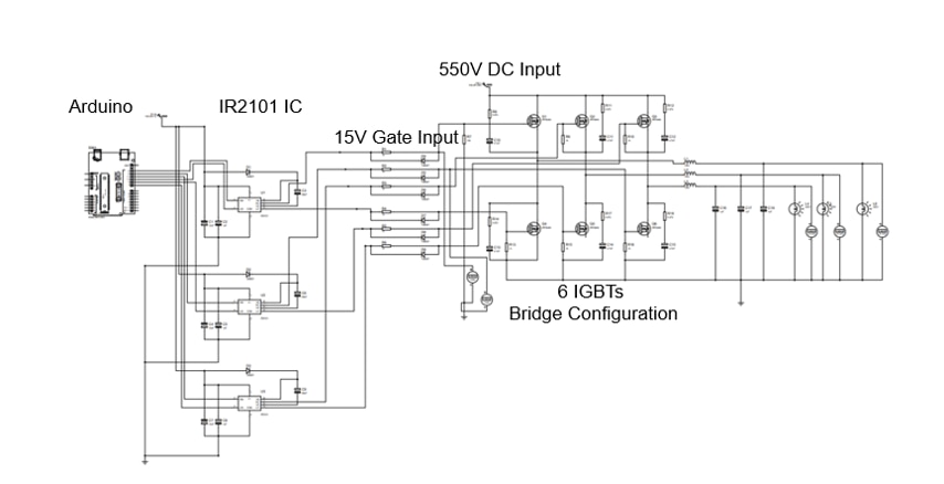
Hello Everyone..! I am using GT60N321 Toshiba make IGBT to control 3 phase motor. I have used 6 IGBTs in full bridge configuration. Gate pulses are given from IR2101 IC (10Volts Output) which in turn driven from Arduino mega. 550Volts DC to be connected at collector terminal of IGBTs. We were expecting 400V AC output. But we are not getting full output as expected. Output is limited to 22V. Please suggest what could have gone wrong? Suggestion with regard to Schematic, Circuit diagram, Code will be appreciated. My circuit diagram for your reference has been attached. image
  • Sign in to reply
  • Cancel
  • dougw
    dougw over 1 year ago

    I can't read the schematic clearly.

    There is something odd about the schematic. Two of the lower transistors do not appear to be connected to conduct current.

    Also the bridges seem intended to be half bridges on each phase, not full H-bridges, so the circuit won't output AC. At least not if I am reading the grounds properly.

    Maybe a larger discussion is needed to understand all the issues with designing such a circuit at these voltages.

    • Cancel
    • Vote Up 0 Vote Down
    • Sign in to reply
    • Cancel
  • robogary
    robogary over 1 year ago

    The schematic isnt very clear  very hard to read BUT I can share you these insights. 

    The DC link negative side seems to be missing, or maybe in the spaghetti referenced to ground.  

    It kind of looks like the motor Nuetral of a WYE is tied to ground.

    The DC link has to float as well as the motor should be connected delta - the "motor nuetral" is somewhere between DC link + and DC link -.   

    https://duckduckgo.com/?q=3+phase+H+bridge&atb=v314-1&iax=images&ia=images&iai=https%3A%2F%2Fwww.researchgate.net%2Fprofile%2FSiddharth_Tyagi3%2Fpublication%2F332977818%2Ffigure%2Fdownload%2Ffig1%2FAS%3A756856242831360%401557459998703%2F3-phase-H-Bridge-Inverter.ppm

     You also didnt mention the 3phase output frequency that you are targeting for 400V output, and have you verified each phase gating is 120 degrees from each other ?  

    • Cancel
    • Vote Up 0 Vote Down
    • Sign in to reply
    • Cancel
  • Dhruv1253
    Dhruv1253 over 1 year ago in reply to robogary

    ​Guys, please consider the attached images of circuit diagram for your reference. we tried to simulate in proteus, in which motor runs. but physically we observed some issues with inverter module. Its output is not as expected. Rectifier is working fine. Rectifier output is 550 V. which is given to collector of high side IGBTs. 

    ​Expected output at Inverter output side is 400V AC. but we are getting only 10-20Volts output.

    while handling single IGBT, issue we found with GT60N321 IGBTs are:-

    1) When we give 10V Gate, 24V Collector, then we get only 12-13V output at Emitter

    2) When we give 19V Gate, 24V Collector, then we get 23V output at Emitter

     but

    3) When we give 19V Gate, 50V Collector, then still we get 27V output at Emitter. which should not have happened. We expect 48V approx output at emitter.

    Output are being measured using multimeter. In practical we are giving 6 signals from Arduino to 6 IGBTs.  

    ​Arduino code has been attached for your reference. Go through the following link

    https://drive.google.com/drive/folders/1xPWNTgpzAg_rWaKuolom9bMd_bKOaOKf?usp=drive_link

    • Cancel
    • Vote Up 0 Vote Down
    • Sign in to reply
    • Cancel
  • Dhruv1253
    Dhruv1253 over 1 year ago in reply to dougw

    Please see the reply given to @robogary

    • Cancel
    • Vote Up 0 Vote Down
    • Sign in to reply
    • Cancel
  • dougw
    dougw over 1 year ago in reply to Dhruv1253

    I can't access that link.

    What is the voltage at Vb of the IR2101?

    Is it connected to the high collector voltage?

    • Cancel
    • Vote Up 0 Vote Down
    • Sign in to reply
    • Cancel
  • Dhruv1253
    Dhruv1253 over 1 year ago in reply to dougw

    https://drive.google.com/drive/folders/1xPWNTgpzAg_rWaKuolom9bMd_bKOaOKf?usp=sharing

    access this link... 

    Vb is connected to 15V via bootstrap diode.

    Vb is connected to Vs via bootstrap capacitor.

    • Cancel
    • Vote Up 0 Vote Down
    • Sign in to reply
    • Cancel
  • dougw
    dougw over 1 year ago in reply to Dhruv1253

    When the driver chip turns on the gate should be 10V above the emitter and stay 10 V above the emitter as the output voltage of the IGBT (Vs) goes high - due to the boost cap. It sounds like the IGBT can turn on okay but something is preventing the boost cap from boosting the gate voltage. Is the diode to 15V breaking down? What is its voltage rating of the diode?

    • Cancel
    • Vote Up 0 Vote Down
    • Sign in to reply
    • Cancel
element14 Community

element14 is the first online community specifically for engineers. Connect with your peers and get expert answers to your questions.

  • Members
  • Learn
  • Technologies
  • Challenges & Projects
  • Products
  • Store
  • About Us
  • Feedback & Support
  • FAQs
  • Terms of Use
  • Privacy Policy
  • Legal and Copyright Notices
  • Sitemap
  • Cookies

An Avnet Company © 2025 Premier Farnell Limited. All Rights Reserved.

Premier Farnell Ltd, registered in England and Wales (no 00876412), registered office: Farnell House, Forge Lane, Leeds LS12 2NE.

ICP 备案号 10220084.

Follow element14

  • X
  • Facebook
  • linkedin
  • YouTube