element14 Community
element14 Community
    Register Log In
  • Site
  • Search
  • Log In Register
  • About Us
  • Community Hub
    Community Hub
    • What's New on element14
    • Feedback and Support
    • Benefits of Membership
    • Personal Blogs
    • Members Area
    • Achievement Levels
  • Learn
    Learn
    • Ask an Expert
    • eBooks
    • element14 presents
    • Learning Center
    • Tech Spotlight
    • STEM Academy
    • Webinars, Training and Events
    • Learning Groups
  • Technologies
    Technologies
    • 3D Printing
    • FPGA
    • Industrial Automation
    • Internet of Things
    • Power & Energy
    • Sensors
    • Technology Groups
  • Challenges & Projects
    Challenges & Projects
    • Design Challenges
    • element14 presents Projects
    • Project14
    • Arduino Projects
    • Raspberry Pi Projects
    • Project Groups
  • Products
    Products
    • Arduino
    • Avnet Boards Community
    • Dev Tools
    • Manufacturers
    • Multicomp Pro
    • Product Groups
    • Raspberry Pi
    • RoadTests & Reviews
  • Store
    Store
    • Visit Your Store
    • Choose another store...
      • Europe
      •  Austria (German)
      •  Belgium (Dutch, French)
      •  Bulgaria (Bulgarian)
      •  Czech Republic (Czech)
      •  Denmark (Danish)
      •  Estonia (Estonian)
      •  Finland (Finnish)
      •  France (French)
      •  Germany (German)
      •  Hungary (Hungarian)
      •  Ireland
      •  Israel
      •  Italy (Italian)
      •  Latvia (Latvian)
      •  
      •  Lithuania (Lithuanian)
      •  Netherlands (Dutch)
      •  Norway (Norwegian)
      •  Poland (Polish)
      •  Portugal (Portuguese)
      •  Romania (Romanian)
      •  Russia (Russian)
      •  Slovakia (Slovak)
      •  Slovenia (Slovenian)
      •  Spain (Spanish)
      •  Sweden (Swedish)
      •  Switzerland(German, French)
      •  Turkey (Turkish)
      •  United Kingdom
      • Asia Pacific
      •  Australia
      •  China
      •  Hong Kong
      •  India
      •  Korea (Korean)
      •  Malaysia
      •  New Zealand
      •  Philippines
      •  Singapore
      •  Taiwan
      •  Thailand (Thai)
      • Americas
      •  Brazil (Portuguese)
      •  Canada
      •  Mexico (Spanish)
      •  United States
      Can't find the country/region you're looking for? Visit our export site or find a local distributor.
  • Translate
  • Profile
  • Settings
Arduino
  • Products
  • More
Arduino
Arduino Forum Arduino microdrum - HELP
  • Blog
  • Forum
  • Documents
  • Quiz
  • Events
  • Polls
  • Files
  • Members
  • Mentions
  • Sub-Groups
  • Tags
  • More
  • Cancel
  • New
Join Arduino to participate - click to join for free!
Actions
  • Share
  • More
  • Cancel
Forum Thread Details
  • Replies 18 replies
  • Subscribers 392 subscribers
  • Views 2042 views
  • Users 0 members are here
  • microdrum
  • arduino due
Related

Arduino microdrum - HELP

ashleymosey
ashleymosey over 8 years ago

okay so iv started a project were im going to build my own electronic drum kit from the ground up and iv been searching for ways to build a drum module as to buy 1 is expensive and if I can make one then why not


so i did some research and the one that got my attention was the MicroDrum http://microdrum.altervista.org/blog/?doing_wp_cron=1486083012.4330480098724365234375


The MicroDrum is a shield/addon that you attach to the Arduino that with some code on the Arduino converts triggers from a piezo transducer to Midi so it can be understood by software like GarageBand or Addictive Drums that then basically enables me to use an Arduino plus the micro drum with a PC to produce the drum sounds and give me a working electronic drum kit 


Now the Microdrum's PCB is sold on the website but I'm on a budget and its cheaper to make my own and the maker of the Microdrum supply schematics found here: http://microdrum.altervista.org/blog/downloads/?doing_wp_cron=1486083519.0516369342803955078125 along with picture of the PCB but the Schematics are in PDF format so cannon be opened in something like easyeda for example and i tried to copy the schematics over to easyeda but tbh I'm very confused and do not understand the spider web that is happening in the schematics microdrum supplies and when i get the parts in easyeda and place them they look completely different to what's in the original schematics but if i look at the data sheets for each part they match easyeda but not microdrums schematics so im having difficulty copying the data over my knowledge of electronics is enough to just get me by and i think this a little advance for me im hoping someone will be kind enough to help me out il put any usefull links below


Parts List: http://microdrum.altervista.org/wiki/index.php?title=Parts_List

Assembly Guide for if you buy the PCB (has useful images) http://microdrum.altervista.org/wiki/index.php?title=Building_with_the_PCBs

Micro Drum Wiki Main Page: http://microdrum.altervista.org/wiki/index.php?title=Main_Page

Micro Drum Schematics: http://microdrum.altervista.org/blog/schematics/?doing_wp_cron=1486084085.1847140789031982421875


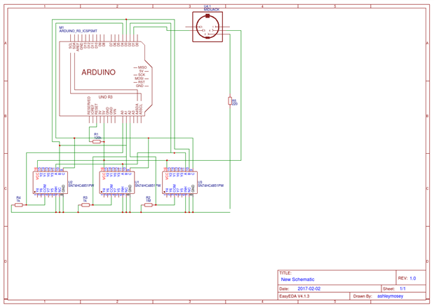
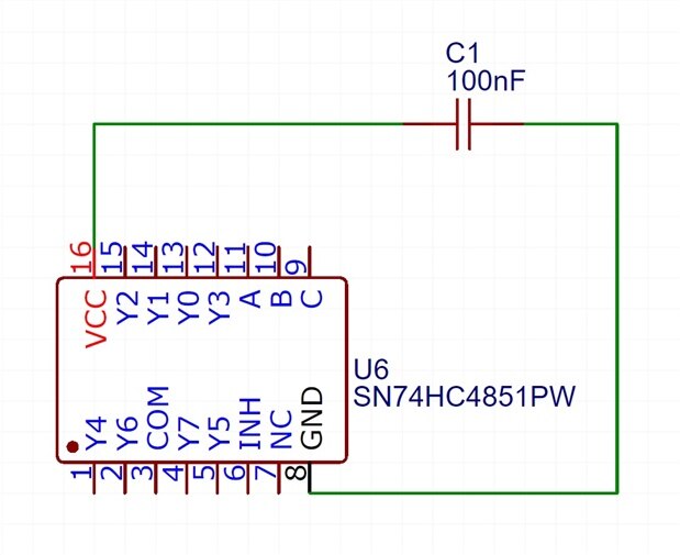
Here is what iv managed to sort out so far but i have no idea if this is correct iv only included 3 Multiplexers because that give me enough ports to connect a standard drumkit and have a spare

image

  • Sign in to reply
  • Cancel

Top Replies

  • dougw
    dougw over 8 years ago in reply to ashleymosey +3
    Piezo sensors can generate high voltages, so you probably need to protect the chips. I show a typical protection circuit in this blog about connecting a piezo disk to an arduino .
  • ashleymosey
    ashleymosey over 8 years ago +2
    https://easyeda.com/editor#id=63924b08d02d44fc9a50f9f875a0448c here is a compleated schematic that's finished from what knowledge iv attained the remaining open pin are all inputs 8 inputs per multiplexer…
  • clem57
    clem57 over 8 years ago +1
    If you want to skip the PCB, no problem. Just follow these http://microdrum.altervista.org/wiki/index.php?title=How_to_Build/Setup_a_microDrum which uses a breadboard instead of PCB. Not as pretty, but…
Parents
  • ashleymosey
    ashleymosey over 8 years ago

    https://easyeda.com/editor#id=63924b08d02d44fc9a50f9f875a0448c here is a compleated schematic that's finished from what knowledge iv attained the remaining open pin are all inputs 8 inputs per multiplexer so positive of the piezo goes to a multiplexer pin and the neg goes to ground if im not mistaken please correct me if im wrong and also let me know if this circuit will work

    • Cancel
    • Vote Up +2 Vote Down
    • Sign in to reply
    • Cancel
  • shabaz
    shabaz over 8 years ago in reply to ashleymosey

    Hi Ashley,

    It looks about right if you're trying to replicate the design, although you're missing 1M resistors between pin 3 on the multiplexer ICs and gnd.

    I'm not sure you need R1 (the resistor connected to Reset on the Arduino) since the Arduino standalone runs fine without this.

    Also, you're missing the connectors to which you will wire your inputs.

    And it is a good idea to add 100nF capacitors across the VCC and GND pins of each of the '4851 ICs.

    Also, the original circuit diagram is ugly, I can understand you're trying to replicate it so it has been entered in a similar way, but for future designs it is best to stick to some conventions (VCC drawn at the top as a horizontal line, GND at the bottom, inputs on the left, outputs on the right).

    Also the piezo issue that dougw mentions should be considered too.


    Finally, it's good you're designing your own board. 20 euro + 10 euro shipping for it is extortionate as far as I am concerned.

    • Cancel
    • Vote Up +1 Vote Down
    • Sign in to reply
    • Cancel
  • ashleymosey
    ashleymosey over 8 years ago in reply to shabaz

    If I'm honest i dont know what resistor 1 to the reset is for I just kinda followed the trend of what other people did, and iv now fixed the resisters from the IC to gnd, and i just left the connectors out for now I just know that all the remaining connections are for Piezo possitives and the negatives go to ground if I'm not mistaken ?? I'm not sure what you mean with the capacitor across the VCC pins and GND they aren't connected already are you suggesting I connect them like so: image

    • Cancel
    • Vote Up 0 Vote Down
    • Sign in to reply
    • Cancel
Reply
  • ashleymosey
    ashleymosey over 8 years ago in reply to shabaz

    If I'm honest i dont know what resistor 1 to the reset is for I just kinda followed the trend of what other people did, and iv now fixed the resisters from the IC to gnd, and i just left the connectors out for now I just know that all the remaining connections are for Piezo possitives and the negatives go to ground if I'm not mistaken ?? I'm not sure what you mean with the capacitor across the VCC pins and GND they aren't connected already are you suggesting I connect them like so: image

    • Cancel
    • Vote Up 0 Vote Down
    • Sign in to reply
    • Cancel
Children
  • shabaz
    shabaz over 8 years ago in reply to ashleymosey

    Hi Ashley,


    Exactly as you've drawn, close to each IC. See figure 3.3.2 here:

    Logic IC Parameters

    • Cancel
    • Vote Up +1 Vote Down
    • Sign in to reply
    • Cancel
element14 Community

element14 is the first online community specifically for engineers. Connect with your peers and get expert answers to your questions.

  • Members
  • Learn
  • Technologies
  • Challenges & Projects
  • Products
  • Store
  • About Us
  • Feedback & Support
  • FAQs
  • Terms of Use
  • Privacy Policy
  • Legal and Copyright Notices
  • Sitemap
  • Cookies

An Avnet Company © 2025 Premier Farnell Limited. All Rights Reserved.

Premier Farnell Ltd, registered in England and Wales (no 00876412), registered office: Farnell House, Forge Lane, Leeds LS12 2NE.

ICP 备案号 10220084.

Follow element14

  • X
  • Facebook
  • linkedin
  • YouTube