Components: 1 Arduino, 4 LDRs, 4 Relays (Omron G5LE-1-36), Relay Protection (4 Transistors, 4 Resistors, 4 Inverting diodes) & 1 Solar Panel Platform (2 DC Motors)
Problem: Not sure how to wire the last part of my solar panel controller correctly!
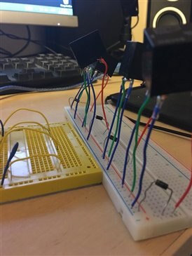
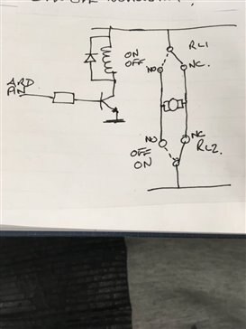
-> Relay Wiring:
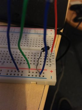
*Is the first blue wire (Pin2) and green wire (Pin1) meant to be on the same rail?
*Is the second blue wire (Pin5) ground?
*Does the diode go between the green wire (Pin1) and the orange wire (Pin4)?
*Going by the mark what way is the diode meant to be facing?
*Datasheet (Pins in regards to datasheet)-> https://eu.mouser.com/datasheet/2/307/en-g5le-1131193.pdf (from this site https://eu.mouser.com/ProductDetail/Omron-Electronics/G5LE-1-36-DC5?qs=JK6Bpmia%2fmtcCWosfO3L%2fQ== )
-> Connection from each of the yellow breadboard yellow wires to each of the Relays? Which of the Relay wires should the yellow wire be connected to?
-> What connections of the relays should I connect to each of the 2 motors (2 Relays per Motor, 2 wires per DC Solar Panel Motor)
-> Is there anything missing?
Details:
Hi everyone!
thanks for viewing my post and seeing what you can do to help out 
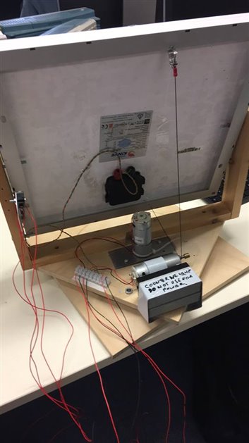
simply put the solar panel as you can see in the first picture has two motors
to control .....1 for vertical movement, 1 for horizontal movement. I am trying
to create a controller for the solar panel essentially! So it can move in the direction
of where there is most light
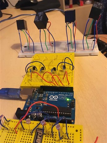
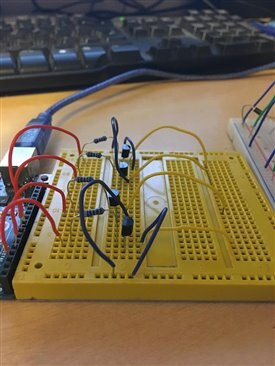
As you can see below the first breadboard is full of LDRs for sensing light so that when programmed
in to the arduino the solar panel will automatically turn to the area where there is most light
(when LDRs are at the corners of the solar panel at the moment just testing).
Beyond the Arduino on the yellow breadboard is a protection circuit for the relay
and on the last white breadboard is where the relays are where they will be connected
to the DC servo motors on the solar panel platform.
As stated before my problem is in wiring things up at the end my coding is
alright.....I think .....lol one thing at a time