This tutorial was extracted from Erich Styger blog http://mcuoneclipse.wordpress.com with his agreement.
Unlike other boards from Freescale, the FRDM-KL25Z has no potentiometer or analog components on it. But in many applications an ADC conversion is needed, so here we go with a tutorial reading in an external potentiometer with Eclipse, CodeWarrior and Processor Expert. For this tutorial I have a 10k Ohm linear potentiometer connected to the Freedom board:
Linear potentiometer with the FRDM-KL25ZFRDM-KL25Z
![]() While this tutorial is for the Freedom KL25Z project, things are generic for any microcontroller supported by Processor Expert. Only the port/pins might be different.
While this tutorial is for the Freedom KL25Z project, things are generic for any microcontroller supported by Processor Expert. Only the port/pins might be different.
The black (GND) and red (3.3V) wires are connected to the ‘full range’ connectors for the potentiometer, while the white wire is connected to the current position pin. The white wire is connected to the ‘Arduino’ A0 pin of the Freedom board:
Schematic with 10k Ohm Potentiometer
Creating the Project
With CodeWarrior for MCU10.3, I create a project with the ‘New Project Wizard’ (menu File > New > Bareboard Project). I give a project name, select my microcontroller (KL25Z), connection (OpenSDA), Toolchain (gcc) and Rapid Application Development (Processor Expert).
Adding ADC Component
From the Components Library I add the ADC component to the project:
Adding ADC Component
![]() If the Component Library view is not open, use the menu Processor Expert > Show Views.
If the Component Library view is not open, use the menu Processor Expert > Show Views.
Configuring ADC Component
With the component added, it shows with an error marker as I need to configure it first:
Added ADC Component
First, to configure the pin to be used. According to the schematics, the A0 pin is connected to ADC0_SE8/PTB0:
Selecting ADC Pin
Next to configure the conversion time. For this I click the ‘…’ button:
![]() I need to click *into* the field to show the ‘…’ button.
I need to click *into* the field to show the ‘…’ button.
Conversion Time Setup
This opens a dialog where I can specify the conversion time. I select one of the available values from the right side (e.g. double clicking on it):
Conversion Time Selection
![]() The Conversion Time specifies how fast the AD conversion shall be performed. This has of course an impact on the timing and quality of the conversion. For this tutorial, we simply select a timing.
The Conversion Time specifies how fast the AD conversion shall be performed. This has of course an impact on the timing and quality of the conversion. For this tutorial, we simply select a timing.
Generating Code
With everything configured, I use the ‘Generate Code’ button:
Code Generation
The generated code ends up in the Generated_Code folder of the project:
Generated Code Folder
In the next step, I’m going to use it in the main() inside the file ProcessorExpert.c.
Doing the Conversion
Instead of typing the code, I can drag&drop the method names to my source:
Drag and Drop of Method
The method Measure() needs an extra boolean argument if it shall wait for the finish of the conversion (yes, I want to wait). And I’m not interested in the error return code, so I cast it to void:
To get the conversion value, the method GetValue16() is used which returns the 16bit result. For the result I define a 16bit global variable:
And do the AD conversion in an endless loop:
With this, it could look like this:
ProcessorExpert.c
Build and Debug
With the menu Project > Build Project I compile my project. I press the ‘Debug’ button I download the program to the board and let it run.
![]() To watch the variable changing in the debugger while it is running, see Live View for Variables and Memory.
To watch the variable changing in the debugger while it is running, see Live View for Variables and Memory.
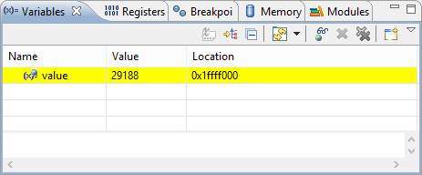
In the Variables View, I can see how the value changes:
Value in Variables View
Using Interrupts
So far I was waiting for the conversion to be finished with the TRUE parameter to the Measure() method. By default, the ADC component already has interrupts enabled:
Interrupts Enabled
If I use interrupts and do not wait for the conversion to be finished, I get notified by the OnEnd() event:
OnEnd Event
Double-Clicking on the OnEnd() method gets me to the Events.c file, where I can fill in the code:
AD1_OnEnd Hook
To keep things simple, I set a boolean flag:
![]() I have marked this variable with volatile as the variable is changed in an interrupt service routine, and used the same time from the main program. The volatile prevents the compiler to keep that variable in a register.
I have marked this variable with volatile as the variable is changed in an interrupt service routine, and used the same time from the main program. The volatile prevents the compiler to keep that variable in a register.
I add this boolean variable to my global variables in Processor Expert.c:
![]() Once things are working, consider to put that AD_finished variable declaration into a header file.
Once things are working, consider to put that AD_finished variable declaration into a header file.
Then I change my loop to start the conversion without waiting, so I can do something else while the conversion is going on:
Multiple Channels
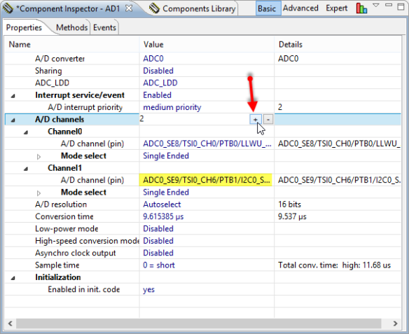
So far I was using a single AD value. But the component (and hardware) can be configured to convert multiple channels. To read in as well the A1 pin which is mapped to PTB1 I use the ‘+’ icon to add another channel:
![]() I need to click into the field to have the ‘+’ and ‘-’ icons.
I need to click into the field to have the ‘+’ and ‘-’ icons.
Added another channel
I can use the same methods as above (Measure() and GetValue16(), but as GetValue16() is using a pointer to an array of values, I need to make sure I pass the right number of items to it:
The component has created a #define for the number of channels for me (CHANNEL_COUNT) which I can use for my value variable:
To the GetValue16() method, I pass the address of the first item:
With this, my code works with multiple channels.
Summary
With Processor Expert, it is not very difficult to use ADC conversion. Once familiar with the concept, it is easy to add multiple channels and to use interrupt synchronization. I do not cover here advanced features like using DMA (as not supported out oft the box with Processor Expert yet), or using different conversion modes. I think this is enough for now to get you started ![]() .
.


