


The RoboSapien 1.0 is ideal for barebones stripping and experimentation, as the motors and switches are set in place and any changes that you wish to be made may easily be done by reassigning their configuration. It is truly ahead of its time in terms of its engineering build and resources pertaining to its documentation can be found on the net for free.
In this documentation, I aim for the following:
- Strip the robot down to bare wires and integrate the use of PIC's to reconfigure its driver
- Map out the control board by reverse engineering the electronics
- Use an application that coordinates with the website API
- Utilize web SSH to send signals to the microcontroller indicating a change or activation of a motor
The process is relatively simple, and a fast project that can be done within 2-3 hours. Without further ado, let's get started.
Step 1: Disassembly
- This part is fairly easy and there is no need for an elaborate explanation. Simply unscrew the front side of the robot's enclosure. The power switch as well as the speakers must be removed as well with screws, but conveniently have extra connection pads in them for you to add to. The main control board is at the back side.
- Afterwards, Remove and disconnect all wires from the board and unscrew it. Pin connections are imbued on the PCB's under side so check that for the connections. For this experiment, we will be using the VCC, GND and IR pins. Solder about 15 cm of wires to each them as such.
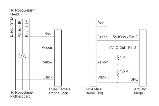
Step 2: Connect to the PIC
- Mount the 3 connections mentioned above to your microcontroller (I used an Arduino Mega atm for this).
The IR signals, per se, are separated by spaces meaning that each bit that passes data will create a high and then a low right after. The pulses will indicate if the bit is 1 or 0.
I experimented quite a bit on coding in order to get the establishment between the two right, and this is what I came up with:
void loop()
{
  unsigned char val = 0;
  unsigned long start, ts, dur;

  while(digitalRead(irPin)) {
  start = micros();
  }

  while(!digitalRead(irPin))
  ts = (micros() - start) / 8;
  }

  for(char b = 7; b >= 0; b--) {
  start = micros();
  while(digitalRead(irPin)) {
  dur = micros() - start;
  }
  if(dur > ts*2)
  val |= 1<<b;
  while(!digitalRead(irPin)) { }
  }

  Serial.println(val, HEX);
}
The output data seems to come out easily, so that was a good start.
Step 3: Web Code Implementation
The microcontroller will enable us to emulate the same binaries that the original remote that came with the packaging gives. Since we were able to pull them from the code used in the previous step, we are now ready for serial communication. The control board must be triggered on remote mode so as to prevent any disruptions when booting up, which afterwards it can be switched back to where you assigned the MCU. Plug the wires to their respective assignments based on the code below. You may add an LED as an optional accessory to indicate if it works. Upload the following code:
#include

volatile int viRobsapienCmd = -1;  // A robosapien command sent over the UART request
#define RSTurnRight       0x80
#define RSRightArmUp      0x81
#define RSRightArmOut     0x82
#define RSTiltBodyRight   0x83
#define RSRightArmDown    0x84
#define RSRightArmIn      0x85
#define RSWalkForward     0x86
#define RSWalkBackward    0x87
#define RSTurnLeft        0x88
#define RSLeftArmUp       0x89
#define RSLeftArmOut      0x8A
#define RSTiltBodyLeft    0x8B
#define RSLeftArmDown     0x8C
#define RSLeftArmIn       0x8D
#define RSStop            0x8E
#define RSWakeUp          0xB1
#define RSBurp            0xC2
#define RSRightHandStrike 0xC0
#define RSNoOp            0xEF

//
#define RSRightHandSweep  0xC1
#define RSRightHandStrike2 0xC3
#define RSHigh5           0xC4
#define RSFart            0xC7
#define RSLeftHandStrike  0xC8
#define RSLeftHandSweep  0xC9

#define RSWhistle         0xCA
#define RSRoar            0xCE

int command, buff[]={
0x80, 0x81, 0x82, 0x83, 0x84, 0x85,
0x86, 0x87, 0x88, 0x89, 0x8A, 0x8B, 0x8C, 0x8D, 0x8E, 0xB1,
0xC2, 0xC0, 0xEF, 0xC1, 0xC3, 0xC4, 0xC7, 0xC8, 0xC9};

int LedControl = 13;     // Show when control on
int IROut= 6;            // Where the echoed command will be sent from
int bitTime=516;          // Bit time (Theoretically 833 but 516)
// works for transmission and is faster
int last;                 // Previous command from IR

//////////////////////////////////////////////////////////////////
// Begin Robosapien specific code
//////////////////////////////////////////////////////////////////
// send the command 8 bits
void RSSendCommand(int command) {
digitalWrite(IROut,LOW);
delayMicroseconds(8*bitTime);
for (int i=0;i<8;i++) {
digitalWrite(IROut,HIGH);
delayMicroseconds(bitTime);
if ((command & 128) !=0) delayMicroseconds(3*bitTime);
digitalWrite(IROut,LOW);
delayMicroseconds(bitTime);
command <<= 1;
}
digitalWrite(IROut,HIGH);
delay(250); // Give a 1/4 sec before next
}

// Set up Robosapien functionality
void RSSetup()
{
pinMode(IROut, OUTPUT);
pinMode(LedControl,OUTPUT);
digitalWrite(IROut,HIGH);

// Make robot burp to indicate setup is complete
RSSendCommand(RSBurp);
}

void setup()
{
Serial.begin(9600);
Serial.println("RobSapien Start");

RSSetup();
}

void loop()
{

}
I added a few annotations along the way to guide you. Although there a couple of mapped out functions, the complete table was not included on the code.
The server functions by utilizing a hexadecimal and a trigger character to the back of the main IRl thereby sending a command to the control board. Line 68 can be changed around as such.
---
And there you have it. You are now able to control your Robosapien via a complex non-tied webserver!