

An Open-Source platform to create digital devices and interactive objects that sense and control physical devices. | Arduino Tutorials | |
| Arduino Projects |
Arduino Comparison Chart: Boards & Modules
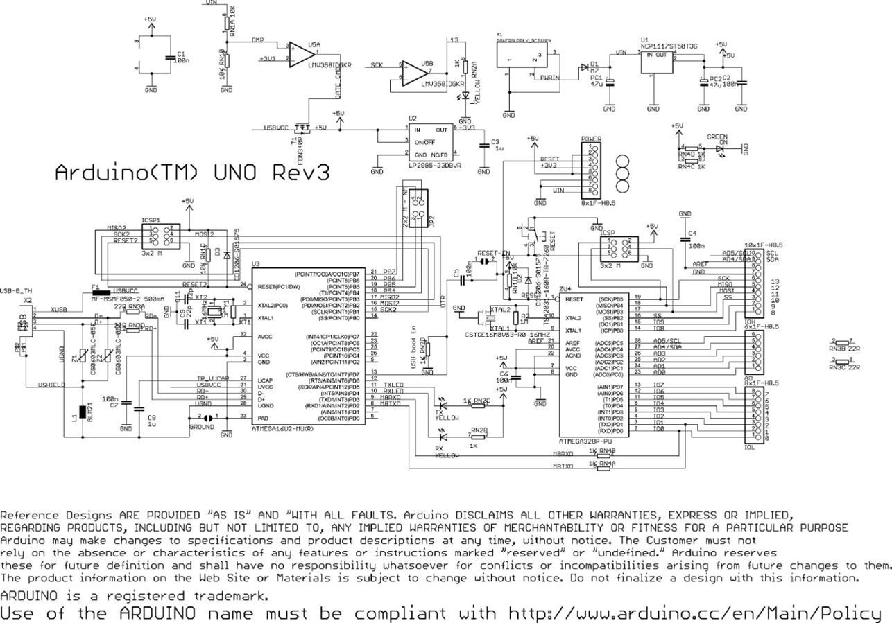
The above schematic is provided to demonstrate what you would need to do to build your own board. Coming up with the Arduino required taking an off the shelf microcontroller, using a lot of extra parts, and putting it together in a way that is simple to use. The genius behind the Arduino is the hard work is done for you, and the microcontroller is designed to be easily programmable through the Arduino IDE.

To do anything useful with the Arduino you will need to know the various parts of the circuit board.
External Power Supply - allows the Arduino to run when its not connected plugged into a USB port for power. It accepts between 7V- 12V of voltage.
USB Plug - This powers the Arduino without needing to use an external power supply and is what you use to upload sketches (program) to the microcontroller, and to communicate with your Arduino sketch (via Serial, println(), etc).
AtMega328 Microcontroller - The brains of the Arduino which you program through the USB plug. It contains three types of memory. It has 32KB of nonvolatile Flash memory. This is used to store applications and is stored on your board even after it is removed from it's power source. 2KB of volatile SRAM memory which is used to store variables used by applications while it's running. 1KB of EEPROM nonvolatile memory. This is used to store data that remains available even after the board is powered down and powered up again.
Pin Functions:
Power Pins (3.3 V, 5 V, GND) - Use these pins to connect to circuitry at 3.3 V, 5V, or GND. Make sure that whatever you power doesn't draw more than a few miliamps.
Serial Out (TX) and Serial In (RX) - Pins (0-1) are RX and TX respectively and used for sending and receiving serial data. This port can be used to send and receive data from a GPS module, bluetooth modules, WIFI modules, etc.
Digital I/O Pins (2-13) - Accept 0 to 5 V input or output. Utilizing tristate logic Arduino makes it easy to change between inputs and outputs in software. You can use this pin as an output where it spits out 5V for a digital 1, or 0 V for a digital 0. You can also configure it to expect a voltage on the pin and that voltage could be interpreted as a 1 or a 0. These pins are used with digitalRead(), digitalWrite (). analogWrite() works only on pins with PWM symbol.
External Interrupts - Pins 2 and 3 can be configured to trigger an interrupt on low value, a rising or falling edge, or a change in value.
PWM Pins - any pins with ~ in front of them can be used to generate pulse modulated square waves. Pins 3, 5, 6, 9, 10, and 11 provide 8-bit PWM output with the analogWrite() function.
Pin 13 - drives the built in LED, that is used by Arduino to receive power and useful for debugging. When pin is HIGH value, the LED is on, when pin is LOW value, it's off.
Analog In Pins - Pins A0 through A5 provide 10 bits of resolution. Accepts 0 to 5 V inputs and is used to measure continuous voltages anywhere from 0 V to 5 V. It is possible to change the upper end of their range using the AREF pin and the analogReference() function.
Analog Reference Pin (AREF) - input pin used optionally if you want external voltage reference for ADC rather than internal Vref. You can configure using an internal register.
Reset Pin - bring this line low to reset the microcontroller. Typically used to add a reset button to shields that block the one on the board.
ATMega168/328 Pin Mapping


Top Comments