

An Open-Source platform to create digital devices and interactive objects that sense and control physical devices. | Arduino Tutorials | |
| Arduino Projects |
The Arduino Vidor 4000 stands out from other boards in the Arduino family due to its inclusion of FPGA. This features should allow audio / video processing for an MKR board that was until now not possible.
The Arduino VIDOR board consists of the following components:
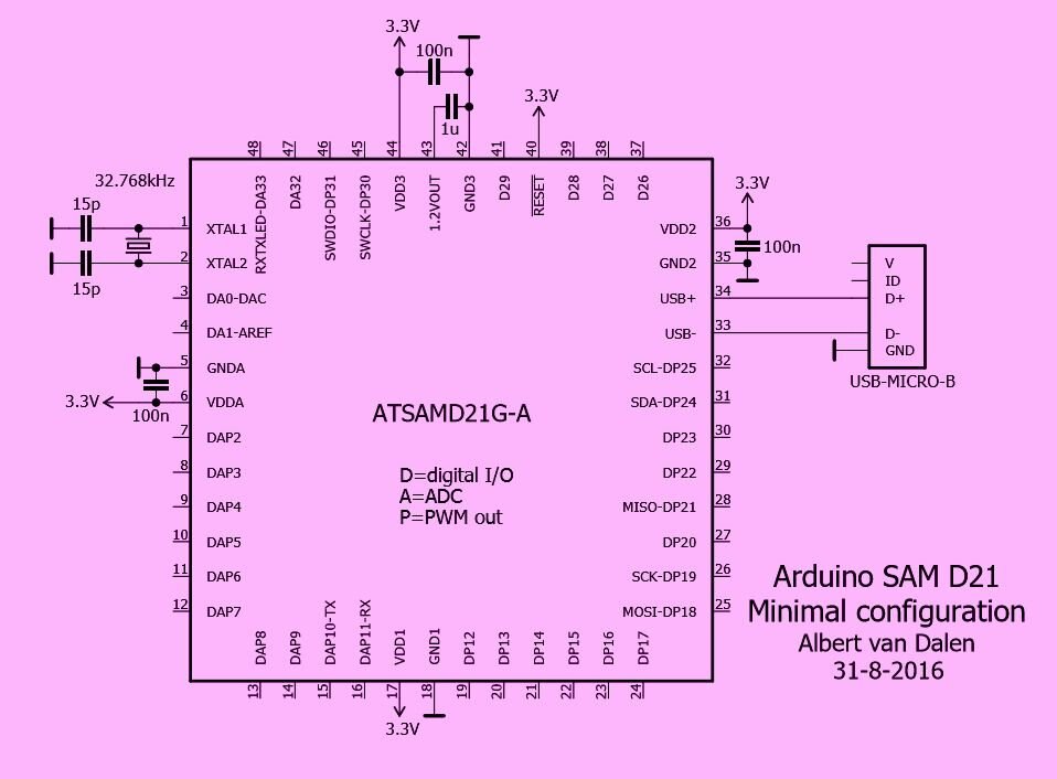
- an ATSAMD21G18A microcontroller with 256k of Flash and 32k of RAM.
- a 10CL016 Cyclone FPGA with 15408 logical elements
- 504kbits of RAM and 56 multiplier 18 × 18
- 16 Mbit SPI FLASH
- 64 Mbits SDRAM (4M x 16 bits) a NINA W102 Wifi / BLE module integrating a ESP32 dual core microcontroller
- ATECC508A cryptographic chip improves processing speed for secure connections.
- MiniPCIe connectors, USB, battery, I2C, MKR, MIPI for a camera, HDMI for video output.
The combination of a SAMD21 microcontroller clocked at 48Mhz, the completely reprogrammable Wifi module, and the FPGA that supports a large number of standard I/O, the board is versatile and should satisfy a large number of uses.

The goal of the ARCHUINO system is to place the FPGA at the center of the system since it has access to almost all resources. The user is free to manage the resources in the FPGA itself or to reroute them to the SAMD21 processor or even the ESP32 of the Wifi module. If the microcontroller and the Wifi module have their own nonvolatile memory for executing a program, the initial configuration of the FPGA is loaded with each power-up since the beginning of the FLASH memory.
Arduino MKR VIDOR 4000:
| Product Name | Quantity | |
|---|---|---|
| Arduino MKR VIDOR 4000 Development Board | 1 | Buy NowBuy Now |
Arduino MKR Shields:
| Product Name | Quantity | |
|---|---|---|
Arduino MKR SD Proto Shield | 1 | Buy NowBuy Now |
Arduino MKR CAN Shield | 1 | Buy NowBuy Now |
Arduino MKR Relay Proto Shield | 1 | Buy NowBuy Now |
Arduino MKR Connector Carrier | 1 | Buy NowBuy Now |
Arduino MKR MEM Shield | 1 | Buy NowBuy Now |
Arduino MKR 485 Shield | 1 | Buy NowBuy Now |
| Arduino MKR ETH Shield | 1 | Buy NowBuy Now |
| Arduino MKR Proto Shield | 1 | Buy NowBuy Now |
| Arduino MKR Proto Large Shield | 1 | Buy NowBuy Now |
The Arduino MKR 4000 VIDOR uses the same pin mapping as the MRK 1000:


Power Pins:
- Li-Po (3.7V) - You can power the board by connecting a Lithium polymer battery (shown to the right) with a nominal voltage of 3.7.
- Vin - The board can be powered by a regulated 5V supply with a maximum voltage of 6V for this Pin.
- 5V - When the board is powered by USB, you can use this pin get +5V to power other circuit
- Vcc - This pin uses the on board regulator IC to output a regulated 3.3V
- GND - Ground Pins
Reset Pin - Bring this line LOW to reset the microcontroller. Typically used to add a reset button to shields which block the one on the board.
Analog Pins (Pins A0-A06) - The 7 analog pins are used to emasure analog voltage in the range 0- 3.3V with a resolution of 10 bit.
DAC0 Pin - The DAC pin is just above the Analog Pins and is used provide an analog voltage based in the digital input with a resolution of 10bit.
Digital I/O Pins (Pins 0-14) - Below the analog pins on the left and just below the reset are digital pins that can be used as either input or output pins. Low is at 0V and high is at 3.3V.
Serial Rx, Tx Pins (Pins 13, 14) - Pins 13 and 14 are used to Receive (Rx) and Transmit (Tx) TTL serial data. These pins are connected to the corresponding pins of the FTDI USB-to-TTL serial chip.
External Interrupts (Pins 0,1, 4, 5,6, 7, 8, A1, A4) - These pins can be used to trigger an interrupt on a low value, a rising or falling edge, or a change in value. See attachInterrupt()function for details.
PWM Pins (Pins 0, 1, 2, 3, 4, 5, 6, 7, 8, 10, A3, A4) - These pins provide 8-bit PWM output with the analogWrite () function.
SPI (Pin 8 - MOSI, Pin 9 - SCK, Pin 10 - MISO) - These pins support SPI Communication
LED - There is a built-in LED connected to digital pin 13. When the pin is HIGH value, the LED is on, when the pin is LOW, it's off.
I2C Pins (Pin 11 is SDA and Pin 12 is SCL) - Pin 11 (SDA) and Pin 12(SCL) support I2C (TWI) communication using the Wire library (documentation on the Wiring website).
AREF Pin - Reference voltage for the analog inputs. Used with analogReference().
The low power, high performance ARM Cortex-MO+ is ideal for a wide range of home automation, consumer, metering, and industrial applications. Its the same SAMD21 as the MKR 1000, MKR Zero, and Arduino/Genuino Zero boards. A unique feature of the SAMD21 chip is SERCOM, a set of six configurable serial interfaces. These can be turned into either a UART, I2C master, I2C slave, SPI master, and SPI slave. Additionally it features a 32-bit Real-Time Clock and calendar, 20 PWM channels, one 14-channel 12-bit ADC, on 10-bit DAC.
| ATSAMD21G18A Overview | |
|---|---|
| Architecture | ARM Cortex-MO+ |
| Voltage Range | 1.62-3.63V |
| Bus Size | 32-Bit |
| Max CPU Speed | 48MHz |
| Internal Oscillator | 21khz, 23Khz ULP, 8Mhz |
| Program Memory Size | 256KB |
| SRAM | 32KB |
| EEPROM | 32KB (emulated from Flash) |
| GPIO | 38 |
| ADC Channels | 14 |
| ADC Resolution | 12-bit |
| Digital-to-Analog Converter (DAC) | Yes |
| USB Controller | Yes |
| Direct Memory Access (DMA) | 12 Channel |
| Peripheral Touch Controller | Yes |
| Inter-IC Sound 12S | Yes |
32 bits, 48 Mhz
The 32 bit architecture allows you to process your instructions faster at double the speed of an 8-bit AVR. While the AVR must process data in 8-bit, the 32-bit architecture allows the SAMD21G to process data in one large chunk.
Memory Map:

USB Controller
Like the ATmega32U4 used on the Leonardo, ATSAMD21 comes with an integrated USB controller, allowing it to be used as either a USB device or host. In device mode it configures itself as a USB CDC (communication device class) so that your computer talks to it as if it were a serial port. This allows the SAMD21 to emulate a mouse, keyboard, or controller, and also work as a mass flash storage. If used as a USB host it can connect to keyboard or mouse, as well as, save data to a USB flash drive. However, to act as a host requires extra power supply.
Real-Time Clock
The SAMD21 has a separate real time clock (RTC), powered by an on board 32.78 crystal, that runs at a full 48 MHz. Also, almost every pin is tied to timer-counter, giving you a lot more PWM-capable I/O pins so you'll have plenty of options for dimming lights or controlling motors.
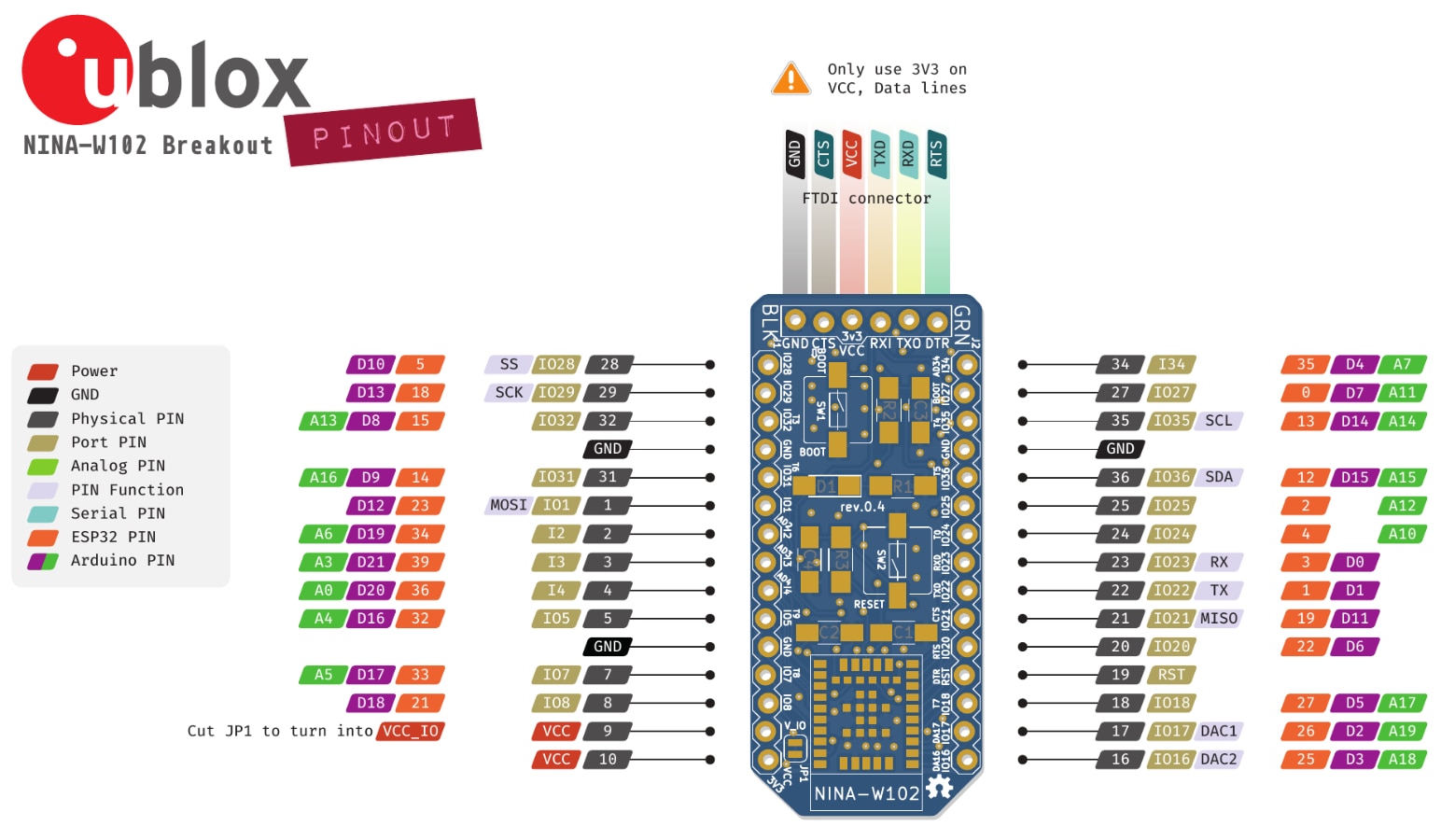
ESP32 Module by u-blox
The MKR WiFi 1010 adds an ESP32 module by u-blox which is a notable improvement from the MKR1000 Wifi. The NINA-W102 Module provides low power 2.4 Ghz 802.11 b/g/n WiFi, dual-mode bluetooth v. 4.2, and RF communication through an internal PIFA antenna. This multiradio MCU integrates a powerful MCU with and a radio for wireless communication. Its open CPU architecture supports advanced applications on a 32-bit mcu. Radio is supported for 802.11 b/g/n WiFi in the 2.4 Ghz band, Bluetooth BR/EDR, and Bluetooth low energy. The ESP32-W10 module has applications for automotive, smart cities, autonomous vehicles, medical technology, home and building automation.
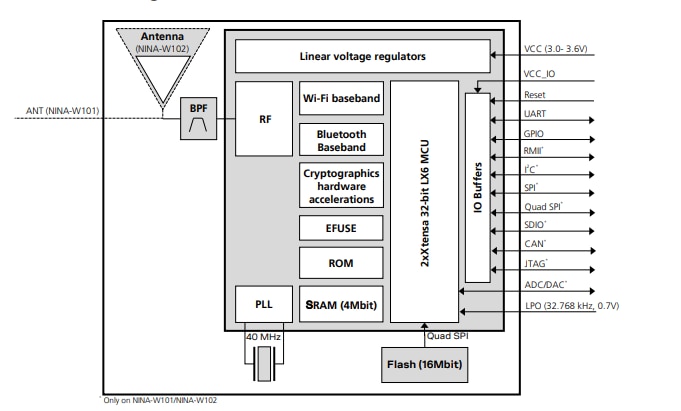
Block Diagram:
| WiFi | Bluetooth BR/EDR | Bluetooth Low Energy |
|---|---|---|
| IEE 802.11b/g/n | Bluetooth v4.2+ EDR Max. number of slaves: 7 | Bluetooth 4.2 BLE dual-mode |
Band support 2.4 GHz, channel 1-13* | Band support 2.3 GHz, 79 channels | Band support 2.4 GHz, 40 channels |
Maximum conducted output power 16 dBm | Maximum conducted output power 5 dBm | Maximum conducted output power 5 dBm |
Maximum radiated output power 19 EIRP** | Maximum radiated output power 8 dBm EIRP** | Maximum radiated output power 8 dBm EIRP** |
Conducted Sensitivity -96 dBm | Conducted Sensitivity -90 dBm | Conductivity -90 dBM |
Data Rates: IEEE 802.11b: 1/2/5.5/11 Mbit/s IEEE 802.11g: 6/9/12/18/24/36/48/54 Mbit/s IEEE 802.11n: MSC 0-7, HT20 (6.5-72 Mbit/s) | Data Rates: 1/2/3 Mbit/s | Data Rates 1 Mbit/s |
* Depending on location (country, region) channels 12-13 must be disabled and support the country determination algorithm for supporting
**RF antenna including maximum antenna gain (3 dBi)
EEC502
Another key feature of the MKR WiFi 1010 is that it has an integrated Cryptochip, Microchip ECC508, for secure communication using SHA 256 encryption.
Reference links:
- Getting Started with MKR Vidor 4000: https://www.arduino.cc/en/Guide/MKRVidor4000
- FPGA HDL Basics: https://www.arduino.cc/en/Tutorial/VidorHDL
- Hands-On Bald Engineer: https://www.baldengineer.com/arduino-mkr-vidor-4000-hands-on.html
- Programming the FPGA Part 1 (French - Use Google Translate):https://systemes-embarques.fr/wp/archives/mkr-vidor-4000-programmation-du-fpga-partie-1/
- Programming the FPGA Part 2 (French - Use Google Translate):https://systemes-embarques.fr/wp/archives/mkr-vidor-4000-programmation-du-fpga-partie-2/
- Generating a DVI frame with an FPGA (French - Use Google Translate): https://systemes-embarques.fr/wp/archives/generation-dune-trame-dvi-avec-un-fpga/
- Displaying a serial terminal on a DVI output (French - Use Google Translate): https://systemes-embarques.fr/wp/archives/affichage-dun-terminal-serie-sur-une-sortie-dvi/
Github links:
This repository includes FPGA IP Blocks compatible with the Arduino Vidor family of products and is aimed to users already familiar with FPGA development process: https://github.com/vidor-libraries/VidorFPGA
Enables network connection (local and Internet) with the Arduino MKR WiFi 1010, Arduino MKR VIDOR 4000 and Arduino UNO WiFi Rev.2: https://github.com/arduino-libraries/WiFiNINA
Source code and configuration files of the Arduino Core for Atmel's SAMD21 processor: https://github.com/arduino/ArduinoCore-samd
| SAM-D21-Family-Datasheet-DS40001882C.pdf | |
| NINA-W10_DataSheet_(UBX-17065507).pdf | |
| 20005927A.pdf | |
| c10lp-51002.pdf | |


