element14 Community
element14 Community
    Register Log In
  • Site
  • Search
  • Log In Register
  • Community Hub
    Community Hub
    • What's New on element14
    • Feedback and Support
    • Benefits of Membership
    • Personal Blogs
    • Members Area
    • Achievement Levels
  • Learn
    Learn
    • Ask an Expert
    • eBooks
    • element14 presents
    • Learning Center
    • Tech Spotlight
    • STEM Academy
    • Webinars, Training and Events
    • Learning Groups
  • Technologies
    Technologies
    • 3D Printing
    • FPGA
    • Industrial Automation
    • Internet of Things
    • Power & Energy
    • Sensors
    • Technology Groups
  • Challenges & Projects
    Challenges & Projects
    • Design Challenges
    • element14 presents Projects
    • Project14
    • Arduino Projects
    • Raspberry Pi Projects
    • Project Groups
  • Products
    Products
    • Arduino
    • Avnet & Tria Boards Community
    • Dev Tools
    • Manufacturers
    • Multicomp Pro
    • Product Groups
    • Raspberry Pi
    • RoadTests & Reviews
  • About Us
  • Store
    Store
    • Visit Your Store
    • Choose another store...
      • Europe
      •  Austria (German)
      •  Belgium (Dutch, French)
      •  Bulgaria (Bulgarian)
      •  Czech Republic (Czech)
      •  Denmark (Danish)
      •  Estonia (Estonian)
      •  Finland (Finnish)
      •  France (French)
      •  Germany (German)
      •  Hungary (Hungarian)
      •  Ireland
      •  Israel
      •  Italy (Italian)
      •  Latvia (Latvian)
      •  
      •  Lithuania (Lithuanian)
      •  Netherlands (Dutch)
      •  Norway (Norwegian)
      •  Poland (Polish)
      •  Portugal (Portuguese)
      •  Romania (Romanian)
      •  Russia (Russian)
      •  Slovakia (Slovak)
      •  Slovenia (Slovenian)
      •  Spain (Spanish)
      •  Sweden (Swedish)
      •  Switzerland(German, French)
      •  Turkey (Turkish)
      •  United Kingdom
      • Asia Pacific
      •  Australia
      •  China
      •  Hong Kong
      •  India
      •  Korea (Korean)
      •  Malaysia
      •  New Zealand
      •  Philippines
      •  Singapore
      •  Taiwan
      •  Thailand (Thai)
      • Americas
      •  Brazil (Portuguese)
      •  Canada
      •  Mexico (Spanish)
      •  United States
      Can't find the country/region you're looking for? Visit our export site or find a local distributor.
  • Translate
  • Profile
  • Settings
Avnet Boards Forums
  • Products
  • Dev Tools
  • Avnet & Tria Boards Community
  • Avnet Boards Forums
  • More
  • Cancel
Avnet Boards Forums
MaaXBoard Hardware Design MaaxBoard-RT: two SPI = DualSPIder - works
  • Forum
  • Documents
  • Members
  • Mentions
  • Sub-Groups
  • Tags
  • More
  • Cancel
  • New
Join Avnet Boards Forums to participate - click to join for free!
Actions
  • Share
  • More
  • Cancel
Forum Thread Details
  • Replies 4 replies
  • Subscribers 333 subscribers
  • Views 949 views
  • Users 0 members are here
  • SPI speed
  • MaaXBoard-RT
  • Maaxboard RT
  • SPI slave
  • DualSPIder
  • spi master
  • performance
Related

MaaxBoard-RT: two SPI = DualSPIder - works

tjaekel
tjaekel over 2 years ago

I found a second SPI on J1 header.
So, I have now implemented the "DualSPIder".

What is DualSPIder?

It is used to compensate "Round Trip Delays":
A SPI Master will send (SCLK, MOSI, CS) but the MISO signal from far end (DUT, "Device Under Test") is delayed (e.g. due to ribbon cable or additional line drivers, or using LVDS...).
So, the SCLK is "mirrored back" at the far end (affected by the same delay due to cable length and drivers) and SCLK', MISO are going into a SPI Slave (still as "synchronous").
So, it compensates the "round trip delay", or the additional delays due to line driver, LVDS interfaces...

DualSPIder approach

Figure 1: DualSPIder approach

One SPI Master and one SPI Slave: the slave receives the "mirrored" SCLK signal so that MISO and SCL are still in sync on MCU receiver (SPI is synchronous!),
never mind how long the cable is; if additional drivers are there or if we use LVDS logic (and converters on both end) - the delay is compensated by this approach.

Changed J1 pin usage

In order to gain the second SPI (LPSPI2) I had to free the Debug UART as LPUART1.
Debug UART is now LPUART6 (see the other pins on J1 and connect to it with your MCU-LINK!).

Testing SPI

if you want to test the SPI via Loopback - to see on Rx what was sent on Tx - you had to use now three wires:

J1, pin 21 - to J1, pin 31
J1, pin 23 - to J1, pin 8
J1, pin 24 - to J1, pin 10

All what you send should also be received (and reported on USB VCP UART).

J1 pin usage

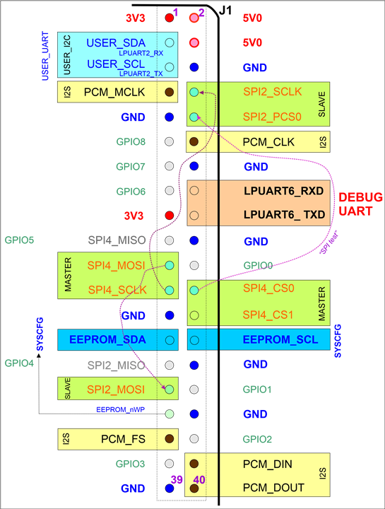
Figure 2: "my" J1 pin usage for DualSPIder and for future use

SPI Performance

I have tested how fast I can go (with this SPI Master plus SPI Slave approach).
ATT: the clock config is modified, in order to increase the speed on SPI: default was just 12 Mbps/MHz.

I can reach:

55.6 MHz for this Master + Slave combination is the maximum I could achieve.
(anyway: way better as the Teensy 4.1 board!)
I use a bit slower: 45.4 MHz, which results in a minimum speed of 4 KHz.

The project is here:

tjaekel/MaaXBoard-RT_SPIder: MaaXBoard-RT SPIder framework (github.com)

  • Sign in to reply
  • Cancel
  • tjaekel
    tjaekel over 2 years ago

    BTW:
    We do not need this PCS0 signal on the SPI Slave, acting as the Slave Rx.
    The "beauty" is:

    • it gains one additional GPIO
    • I have a "shared SPI bus": two slaves with two PCSx signals selected, responding on the same MISO signal
    • using both Slave PCS0 and PCS1 as a HW signals as PCS0 on Slave: I had to combine via an AND gate: either slave can be addressed and
      therefore my SPI Slave Rx has to be selected with either one of the PCSx signals
      (I can save external logic)

    The "trick" is:

    The MCU LPSPI has an AUTOPCS feature:
    You can run a Slave Rx without a PCS, just SCLK and MISO.
    See in Reference Manual, page 5561, paragraph "70.3.2.3 Clocked interface".

    So, it comes to this approach:

    DualSPIder with Slave Rx AUTOPCS

    Remark:
    This AUTOPCS is not supported by the SDK drivers (file: "fsl_lpspi.c"):
    the macro for setting this bit is defined as: LPSPI_CFGR1_AUTOPCS(1)
    but it is never used.

    I have added this line of code in file "fsl_lpspi.c":

    //XXXX: no need for PCS0 on SPI Slave - we use PCS polarity High as indication
    if (slaveConfig->pcsActiveHighOrLow == kLPSPI_PcsActiveHigh)
        base->CFGR1 = base->CFGR1 | LPSPI_CFGR1_AUTOPCS(1);

    So, when I set the logic level for the PCS signal as HIGH (usually it is LOW), I set also this AUTOPCS bit.
    Just to make sure to set also the other requirements, e.g. CPHA = 1.
    See this excerpt from Reference Manual:

    AUTOPCS manual statement

    • Cancel
    • Vote Up 0 Vote Down
    • Sign in to reply
    • Cancel
  • michaelkellett
    michaelkellett over 2 years ago in reply to tjaekel

    Interesting, I have not spotted that feature on a  micro before.

    MK

    • Cancel
    • Vote Up 0 Vote Down
    • Sign in to reply
    • Cancel
  • tjaekel
    tjaekel over 2 years ago in reply to michaelkellett

    BTW: it works a bit similar on an STM32 MCUs:
    if you configure a SPI slave, you can do without to use a HW input signal for Slave Select (nSS, or nCS).
    The STM32 MCU allows to enable/disable a SPI slave also via a SW bit set or unset, when you are ready enable the slave.

    Here, I guess (not tried): the PCSPOL[0] might work in a similar way: if 1 - Slave is enabled, if 0 - Slave is disabled
    (would not receive, e.g. garbage, so, a slave could be in sync with a SPI Tx Master (just active when also sending))

    • Cancel
    • Vote Up 0 Vote Down
    • Sign in to reply
    • Cancel
  • michaelkellett
    michaelkellett over 2 years ago in reply to tjaekel

    Actually it was the clock syncing I hadn't seen before.

    MK

    • Cancel
    • Vote Up 0 Vote Down
    • Sign in to reply
    • Cancel
element14 Community

element14 is the first online community specifically for engineers. Connect with your peers and get expert answers to your questions.

  • Members
  • Learn
  • Technologies
  • Challenges & Projects
  • Products
  • Store
  • About Us
  • Feedback & Support
  • FAQs
  • Terms of Use
  • Privacy Policy
  • Legal and Copyright Notices
  • Sitemap
  • Cookies

An Avnet Company © 2025 Premier Farnell Limited. All Rights Reserved.

Premier Farnell Ltd, registered in England and Wales (no 00876412), registered office: Farnell House, Forge Lane, Leeds LS12 2NE.

ICP 备案号 10220084.

Follow element14

  • X
  • Facebook
  • linkedin
  • YouTube