Do you know that this NXP MCU has TWO ways to use GPIOs?
There are regular GPIOs (pins) but also "Fast GPIO" pins.
Those "Fast GPIO" pins are tightly coupled GPIOs:
The CM7 (or CM4) can set/clear/toggle a GPIO much faster: the clock needed for those "Fast GPIOs" is the same as the MCU core clock (full speed).
So, the action on GPIO is done with the same speed as the SW runs on CM7/CM4.
A regular GPIO might reach a speed (if you try to toggle "full speed" via SW) of 6..15 MHz.
But a "Fast GPIO" can toggle up to 250 MHz (but see comments below).
Regular GPIOs use a different clock source, much slower and accessing GPIO registers is much slower (to set/clear/toggle).
Usually, just regular GPIOs are configured or the SDK API functions access just as regular GPIO.
For "Fast GPIO" you had to code yourself properly.
How to configure "Fast GPIO" pins?
All pins can be used as regular GPIO, but NOT all pins can be used as "Fast GPIO":
See the "GPIO_MUX2" and "GPIO_MUX3" in the reference manual, or as summary:
- several GPIO_EMC_B1_xx and GPIO_EMC_B2_xx pins can be used as "Fast GPIO" (as GPIO_MUX2)
- almost all GPIO_AD_xx pins can be used as "Fast GPIO" (as GPIO_MUX3)
- but any other pin cannot be a "Fast GPIO" (e.g. _DISP_xx)
- some pins have alternative options for fast or regular, see the different GPIO numbering (some pins appear as two different GPIOs possible, select the "GPIO_MUXx_xx" one)
In order to use "Fast GPIO" you have to do:
- configure a pins as "....GPIO_MUXx_IOxx" (2 or 3)
- set a GPR40...GPR43 register in IOMUXC_GPR to enable the "Fast GPIO" access (from MCU), as CM7_GPIO... (4x 16bit to select as a "Fast GPIO", max. 64 "Fast GPIO possible, if available on headers)
- use a different GPIO_Base when set/clear/toggle such a "Fast GPIO" pin, e.g. instead of GPIO2, you use CM7_GPIO2
"pin_mux.c":
Here, how I prepare a "Fast GPIO" in the pin_mux:
/* configure GPIOs */#if 1 IOMUXC_GPR->GPR40 = 0x00008000; /* select FastGPIO, CM7_GPIO2, bit 15 */
GPIO_PinInit(CM7_GPIO2, 15U, &USER_GPIO_config);
IOMUXC_SetPinMux( IOMUXC_GPIO_EMC_B2_05_GPIO_MUX2_IO15, /* configured as GPIO */ 0x0U);
IOMUXC_SetPinConfig( IOMUXC_GPIO_EMC_B2_05_GPIO_MUX2_IO15, 0x03U); /* fast slew rate, high drive strength */#else /* as normal GPIO */ GPIO_PinInit(GPIO8, 15U, &USER_GPIO_config);
IOMUXC_SetPinMux( IOMUXC_GPIO_EMC_B2_05_GPIO8_IO15, /* configured as GPIO */ 0x02U);#endif
"User Code":
Bear in mind to use now a different GPIO_Base address, example:
ITCM_CM7 ECMD_DEC_Status CMD_test(TCMD_DEC_Results *res, EResultOut out)
{
__asm volatile ( "cpsid i" ::: "memory" );
__asm volatile ( "dsb" );
__asm volatile ( "isb" );
for (i = 0; i < 16; i++)
{
/* this results just in 6.6 MHz and not equal pulses! */
////GPIO_PortClear(GPIO8, 1U << 16U);
////GPIO_PortSet(GPIO8, 1U << 16U);
/* this is better: with regular pulses - 15 MHz */
////GPIO_PinWrite(GPIO2, 15, 0);
////GPIO_PinWrite(GPIO2, 15, 1);
/* fast GPIO: but also just 16 MHz */
////GPIO_PinWrite(CM7_GPIO2, 15, 0);
////GPIO_PinWrite(CM7_GPIO2, 15, 1);
////CM7_GPIO2->DR_TOGGLE = 0x8000; //71 MHz, but not all pulses, not periodic! - scope issue?
CM7_GPIO2->DR_CLEAR = 0x8000; //100..125 MHz, short low pulses, longer high pulses - scope issue?
__NOP();
__NOP();
__NOP();
CM7_GPIO2->DR_SET = 0x8000;
__NOP(); //if too fast: works only once - scope issue?
/* with these 4 noops - it looks good: 83 MHz and symmetrical pulses, 50% duty cycle */
/* just 6 MHz */
//GPIO_PinWrite(GPIO8, 15, 0);
//GPIO_PinWrite(GPIO8, 15, 1);
////GPIO_PinWrite(GPIO9, 30, 0);
////GPIO_PinWrite(GPIO9, 30, 1);
}
__asm volatile ( "cpsie i" ::: "memory" );
return CMD_DEC_OK;
}
Code Execution Speed:
Potentially, if you use functions from the SDK library, these are (potentially) located on the external Hyperflash.
So, they are not executed with max. speed, e.g. compared to execution of code which would be located on internal ITCM RAM.
The same for the function where you toggle the GPIOs: also this function might be located on external Hyperflash and therefore all the instructions inside your functions are "slow".
Therefore, I use a macro "ITCM_CM7" in order to force that this code is stored and executed from internal ITCM RAM:
#define ITCM_CM7 __attribute__((section(".ramfunc.$SRAM_ITC_cm7")))
Remarks:
I think, a "Fast GPIO" can toggle with a speed of max. 250 MHz (four MCU clock cycles for an instruction).
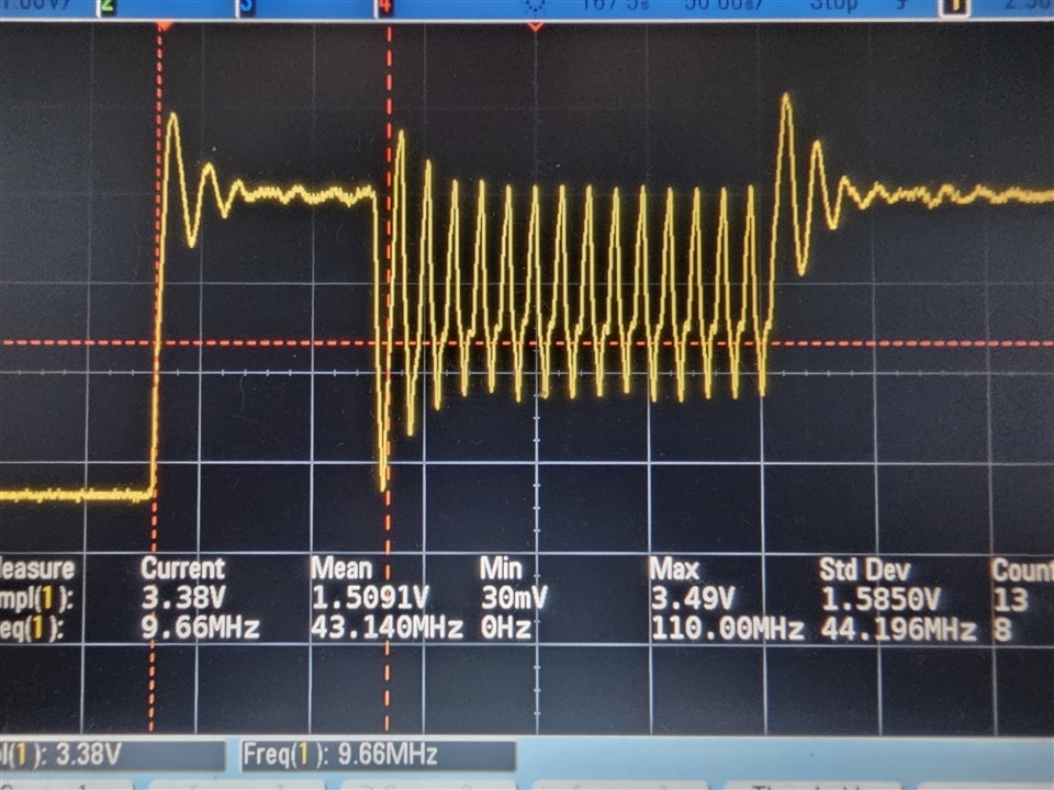
But: what I have seen (on scope and on comments in Internet): the faster you toggle such a "Fast GPIO" - the more it becomes a "sine wave":
It is not really anymore a rectangular pulse, with low and high, instead it can start to be "smeared", looking like a sine wave.
Also the low level, e.g. <0.8V might not be reached anymore (the pin cannot discharge the wires and scope probes).
It could be an issue with my scope (just 500 MHz bandwidth), but eventually the signals generated with such a speed (e.g. > 100 MHz) are not really "digital" anymore.
Please, check the signal integrity.
Fast Slew Rate and High Driver Strength:
You should also configure the Slew Rate and Drive Strength (in "pin_mux.c"), set both to Fast and High.
Further Information:
Here some other helpful info links:
https://community.nxp.com/t5/i-MX-RT-Knowledge-Base/RT1060-Normal-GPIO-vs-Fast-GPIO/ta-p/1119856
https://www.youtube.com/watch?v=nLInUIboLR0

Figure: how it looks for me on scope with "Fast GPIO":
watch the waveform and also the "offset" for the low level signals...
For my purpose: when I can toggle a GPIO with 80 MHz and the signal looks still "good" - I am fine.
(even faster would be possible but signal might become "looking strange")
