FYI,
I am going to create a breakout board (HAT), a PCB, in order to have SPI and QSPI interfaces on headers for this MaaxBoard-RT board (using J1 and J15).
The board should have these "features":
- "DualSPI":
SPI2 is master (Tx only), SPI4 is slave (Rx only) (uni-directional use), using a "delayed" SCLK' signal (compensate "round trip delay")
SPI4 slave (Rx) will not use a PCS (nCS) HW signal (SW based enable)
main requirement to have SPI with "delay compensation" for external devices connected (2x on same SPI bus) - optional to use LPSPI2 as bi-directional master/slave
- LPSPI1:
optional: a full bi-directional master/slave (in addition to all other SPIs and QSPI) - EEPROM:
Use I2C6 for an I2C flash device (persistent storage of SYSCFG, man pages, optional "plug-in" code, "device tree"... - like on Raspberry Pi) - LPUART2/SPDIF_IN and _OUT, I2C3:
provide as header pins, e.g. for user UART, SPDIF - I2C5:
optional I2C, but shared with onboard I2C DAC (and with 2K2 pull-up already on MaaxBoard-RT) - I2S Master:
provide the PCM signals as Master Out for an external DAC (in addition to onboard DAC) - PDM:
one stereo channel for external MICs (as addition/alternative to onboard MICs) - ACMP signals: keep the Analog Comparator signals available
- QSPI on header as: SW GPIO or FLEXIO2 QSPI
SW GPIO QSPI should pin-compatible with SPI interface (FLEXIO2 would not)
my main requirement to have QSPI for an external device - QSPI as FLEXIO:
a QSPI flash on HAT board (for testing, for additional code/data, in parallel with header, two nCS signals for onboard QSPI and header QSPI) - free pins used as GPIO
- RESET signals as GPIO out, INT signals as GPIO in, for external device connected
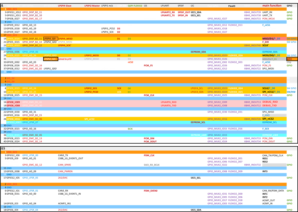
Here is the PinMux Table (how I want to use the MaaxBoard-RT header pins):

Figure 1: MaaxBoard-RT HAT header pins and pinmux functions
Schematics for it might follow...
You could use this table also as reference for the pins and what might be possible with those (pinmux).

