element14 Community
element14 Community
    Register Log In
  • Site
  • Search
  • Log In Register
  • Community Hub
    Community Hub
    • What's New on element14
    • Feedback and Support
    • Benefits of Membership
    • Personal Blogs
    • Members Area
    • Achievement Levels
  • Learn
    Learn
    • Ask an Expert
    • eBooks
    • element14 presents
    • Learning Center
    • Tech Spotlight
    • STEM Academy
    • Webinars, Training and Events
    • Learning Groups
  • Technologies
    Technologies
    • 3D Printing
    • FPGA
    • Industrial Automation
    • Internet of Things
    • Power & Energy
    • Sensors
    • Technology Groups
  • Challenges & Projects
    Challenges & Projects
    • Design Challenges
    • element14 presents Projects
    • Project14
    • Arduino Projects
    • Raspberry Pi Projects
    • Project Groups
  • Products
    Products
    • Arduino
    • Avnet Boards Community
    • Dev Tools
    • Manufacturers
    • Multicomp Pro
    • Product Groups
    • Raspberry Pi
    • RoadTests & Reviews
  • About Us
  • Store
    Store
    • Visit Your Store
    • Choose another store...
      • Europe
      •  Austria (German)
      •  Belgium (Dutch, French)
      •  Bulgaria (Bulgarian)
      •  Czech Republic (Czech)
      •  Denmark (Danish)
      •  Estonia (Estonian)
      •  Finland (Finnish)
      •  France (French)
      •  Germany (German)
      •  Hungary (Hungarian)
      •  Ireland
      •  Israel
      •  Italy (Italian)
      •  Latvia (Latvian)
      •  
      •  Lithuania (Lithuanian)
      •  Netherlands (Dutch)
      •  Norway (Norwegian)
      •  Poland (Polish)
      •  Portugal (Portuguese)
      •  Romania (Romanian)
      •  Russia (Russian)
      •  Slovakia (Slovak)
      •  Slovenia (Slovenian)
      •  Spain (Spanish)
      •  Sweden (Swedish)
      •  Switzerland(German, French)
      •  Turkey (Turkish)
      •  United Kingdom
      • Asia Pacific
      •  Australia
      •  China
      •  Hong Kong
      •  India
      •  Korea (Korean)
      •  Malaysia
      •  New Zealand
      •  Philippines
      •  Singapore
      •  Taiwan
      •  Thailand (Thai)
      • Americas
      •  Brazil (Portuguese)
      •  Canada
      •  Mexico (Spanish)
      •  United States
      Can't find the country/region you're looking for? Visit our export site or find a local distributor.
  • Translate
  • Profile
  • Settings
Avnet Boards Forums
  • Products
  • Dev Tools
  • Avnet Boards Community
  • Avnet Boards Forums
  • More
  • Cancel
Avnet Boards Forums
MaaXBoard Hardware Design MaaXBoard OSM93 and location of J15 2 pin connector
  • Forum
  • Documents
  • Members
  • Mentions
  • Sub-Groups
  • Tags
  • More
  • Cancel
  • New
Join Avnet Boards Forums to participate - click to join for free!
Actions
  • Share
  • More
  • Cancel
Forum Thread Details
  • Replies 4 replies
  • Subscribers 323 subscribers
  • Views 354 views
  • Users 0 members are here
  • osm93
  • Maaxboard OSM93
  • BBSM
  • J15
Related

MaaXBoard OSM93 and location of J15 2 pin connector

WilliamEllis
WilliamEllis 3 months ago

Hi,

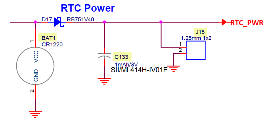
The "MaaXBoard OSM93 Development Kit Hardware User Guide" (version 1.0) describes "RTC External Battery Power" as being connected via (verbatim):

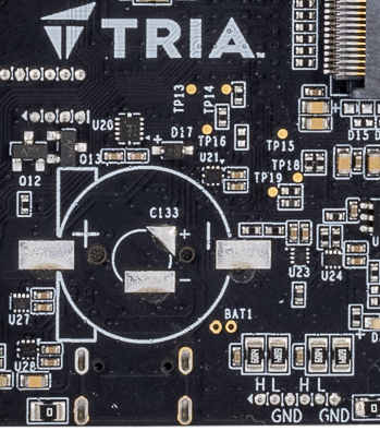
  • The coin cell holder does NOT come pre-populated on board and will need to be installed by the user. Part number of XXXX (Link?) should be used
  • A connector with PN / LINK? should be used to interface with J15 2pin connector.

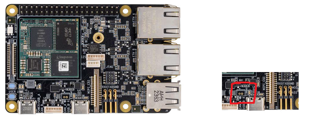
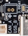
Can anyone advise where the J15 2 pin is? Like, physically, on the board, where is it?! (I can't see it cited anywhere else)

Can anyone advise what the template text "XXXX (Link?)" and "PN / LINK?" is meant to convey? Is there a newer version of this document, perhaps, which has these details?

Bill

  • Sign in to reply
  • Cancel

Top Replies

  • peterfenn
    peterfenn 3 months ago in reply to WilliamEllis +1
    Bill, The production version MaaXBoard OSM93 has the black soldermask as shown in the 2nd photo that you posted. Regarding RTC_PWR : The production version PCB, provides footprints for three different…
  • WilliamEllis
    WilliamEllis 3 months ago

    We notice that "MaaXBoard+OSM93+User+Guide+v1.0.pdf" has this:

    image

    While "FY25_1574_Tria_MaaXBoard_OSM93_Product_Brief-3_vp.pdf" has the below. Note the difference in the highlighted detail in the red box!

    It seems like the board layout has changed/evolved at some stage? Perhaps that changed detail (+ / -)  relates to J15?

    image

    Does anyone have clarity on revisions of the OSM93?

    If we were to buy one of these -- would we get the layout on the top ; or the layout on the bottom?

    • Cancel
    • Vote Up 0 Vote Down
    • Sign in to reply
    • Cancel
  • msaka
    msaka 3 months ago in reply to WilliamEllis

    Hi,

    Can you please clarify the information you need, so I can try to assist.

    Thank you,

    Best regards.

    • Cancel
    • Vote Up 0 Vote Down
    • Sign in to reply
    • Cancel
  • peterfenn
    peterfenn 3 months ago in reply to WilliamEllis

    Bill,

    The production version MaaXBoard OSM93 has the black soldermask as shown in the 2nd photo that you posted.

    Regarding RTC_PWR :
    The production version PCB, provides footprints for three different RTC battery-backup options:

    1) BAT1: CR1220 button battery-holder (not fitted)

    2) C133 : ML414H rechargeable battery footprint (not fitted) 

    3) J15   : 1.25mm pitch, 2-pin header (not fitted)

    image

    These three options can be seen on the marked-up photo of the back of the board shown below

    (BAT1 silkscreen text is misleading, as it is positioned next to the two holes of J15, but battery polarity of all of these footprints is clearly marked) 

    image

    J15 is not labled on the silkscreen, but is indeed the 2-pin header footprint that you queried:

    image
    Regards
    -Peter

    • Cancel
    • Vote Up +1 Vote Down
    • Sign in to reply
    • Cancel
  • WilliamEllis
    WilliamEllis 3 months ago in reply to peterfenn

    Hi, many thanks, this does help clarify! I guess a few details changed between "green" (dev) and "black" (production).

    I would be interested in providing RTC power. Is there a standard / easy / cabling / pin / solution for that? (The reference manual advises, literally "XXXX"!).

    The J15 looks promising - but what would connect in those little gold holes? I would very much prefer a non-soldering solution.

    • Cancel
    • Vote Up 0 Vote Down
    • Sign in to reply
    • Cancel
element14 Community

element14 is the first online community specifically for engineers. Connect with your peers and get expert answers to your questions.

  • Members
  • Learn
  • Technologies
  • Challenges & Projects
  • Products
  • Store
  • About Us
  • Feedback & Support
  • FAQs
  • Terms of Use
  • Privacy Policy
  • Legal and Copyright Notices
  • Sitemap
  • Cookies

An Avnet Company © 2025 Premier Farnell Limited. All Rights Reserved.

Premier Farnell Ltd, registered in England and Wales (no 00876412), registered office: Farnell House, Forge Lane, Leeds LS12 2NE.

ICP 备案号 10220084.

Follow element14

  • X
  • Facebook
  • linkedin
  • YouTube