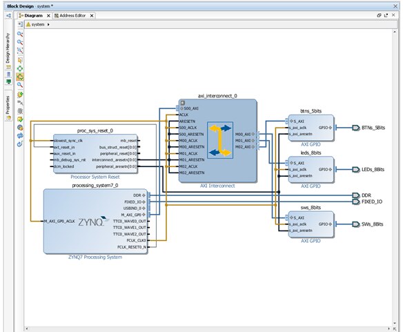
I have a Microzed board with Zynq 7010 and an I/O Carrier Board. I am a beginner and I am trying to create my first project, simply mapping the dip switches (4), push-buttons (4) and LEDs (8) into GPIOs. So I added a processing system. Then I thought about adding 3 AXI_GPIO. First would be of width 4, input only, for the DIP Switches. Second would be of width 4, input only, for the Push Buttons and third would be of width 8, output only, for LEDs.
First question: Do I need to add 3 AXI_Interconnect modules, one for each AXI_GPIO module? That approach seems to be brute force, so next I thought about using only one AXI_GPIO, configured with dual channel, first channel width 8 input only (4 for DIP Switches and 4 for Push Buttons) and second channel width 8 output only (LEDS). Then I think I would need to use only one AXI_Interconnect module, as I have only 1 AXI_GPIO. But previous question stand as: Do I need one AXI_Interconnect for every AXI_GPIO module? Next, in the simple approach using 1 AXI_GPIO, when creating PORT, I could create a LED[7:0] and connect it to second channel. I created a DIP[3:0] and a PB[3:0] and I could not figure out how to connect DIP[3:0] into gpio_io_i[3:0] and PB[3:0] into gpio_io_i[7:4] in the diagram. Any insight on how do I achieve that? Sorry for the simple questions, but as I stated before, I am trying to build my very first project...
Thanks for any input!