element14 Community
element14 Community
    Register Log In
  • Site
  • Search
  • Log In Register
  • About Us
  • Community Hub
    Community Hub
    • What's New on element14
    • Feedback and Support
    • Benefits of Membership
    • Personal Blogs
    • Members Area
    • Achievement Levels
  • Learn
    Learn
    • Ask an Expert
    • eBooks
    • element14 presents
    • Learning Center
    • Tech Spotlight
    • STEM Academy
    • Webinars, Training and Events
    • Learning Groups
  • Technologies
    Technologies
    • 3D Printing
    • FPGA
    • Industrial Automation
    • Internet of Things
    • Power & Energy
    • Sensors
    • Technology Groups
  • Challenges & Projects
    Challenges & Projects
    • Design Challenges
    • element14 presents Projects
    • Project14
    • Arduino Projects
    • Raspberry Pi Projects
    • Project Groups
  • Products
    Products
    • Arduino
    • Avnet Boards Community
    • Dev Tools
    • Manufacturers
    • Multicomp Pro
    • Product Groups
    • Raspberry Pi
    • RoadTests & Reviews
  • Store
    Store
    • Visit Your Store
    • Choose another store...
      • Europe
      •  Austria (German)
      •  Belgium (Dutch, French)
      •  Bulgaria (Bulgarian)
      •  Czech Republic (Czech)
      •  Denmark (Danish)
      •  Estonia (Estonian)
      •  Finland (Finnish)
      •  France (French)
      •  Germany (German)
      •  Hungary (Hungarian)
      •  Ireland
      •  Israel
      •  Italy (Italian)
      •  Latvia (Latvian)
      •  
      •  Lithuania (Lithuanian)
      •  Netherlands (Dutch)
      •  Norway (Norwegian)
      •  Poland (Polish)
      •  Portugal (Portuguese)
      •  Romania (Romanian)
      •  Russia (Russian)
      •  Slovakia (Slovak)
      •  Slovenia (Slovenian)
      •  Spain (Spanish)
      •  Sweden (Swedish)
      •  Switzerland(German, French)
      •  Turkey (Turkish)
      •  United Kingdom
      • Asia Pacific
      •  Australia
      •  China
      •  Hong Kong
      •  India
      •  Korea (Korean)
      •  Malaysia
      •  New Zealand
      •  Philippines
      •  Singapore
      •  Taiwan
      •  Thailand (Thai)
      • Americas
      •  Brazil (Portuguese)
      •  Canada
      •  Mexico (Spanish)
      •  United States
      Can't find the country/region you're looking for? Visit our export site or find a local distributor.
  • Translate
  • Profile
  • Settings
Avnet Boards Forums
  • Products
  • Dev Tools
  • Avnet Boards Community
  • Avnet Boards Forums
  • More
  • Cancel
Avnet Boards Forums
Ultrazed Hardware Design Ultrazed-EV SOM + Carrier card + Xilinx Echo server on SFP issue
  • Forum
  • Documents
  • Members
  • Mentions
  • Sub-Groups
  • Tags
  • More
  • Cancel
  • New
Join Avnet Boards Forums to participate - click to join for free!
Actions
  • Share
  • More
  • Cancel
Forum Thread Details
  • State Suggested Answer
  • Replies 11 replies
  • Answers 2 answers
  • Subscribers 324 subscribers
  • Views 1976 views
  • Users 0 members are here
  • sfp+
  • echo server
  • ultrazed
  • lwip
Related

Ultrazed-EV SOM + Carrier card + Xilinx Echo server on SFP issue

clc1717el14
clc1717el14 over 5 years ago

Hi,

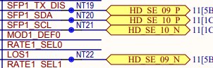
I am trying to enable the SFP+ interface 1 by connecting it by RJ45 to SFP+ converter and run the XIlinx echo server on it.

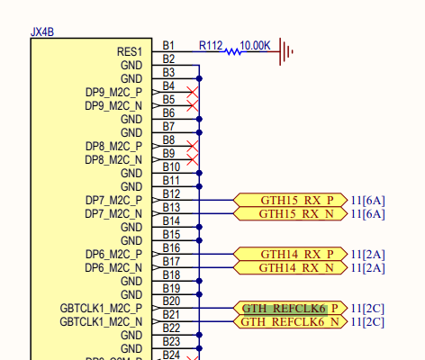
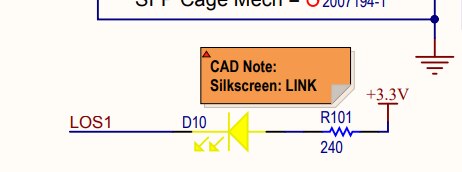
In my Vivado design, I used the AXI 1G/2.5G Ethernet subsystem with the GT reference clock set to 125mhz and GT location set to X0Y4.  For the 125mhz clock, I routed from pins B10 and B9 from the board.  The SFP+ rates are left at the default settings.  The D10 LED is lit up when the RJ45 is connected via SFP+ converter to the SFP+ 1 cage.


Unfortunately the echo server program stops after the lwip_init() function and cannot proceed further. Thus the board is not assigned any IP address.

Does anyone know if I have missed something out?  I can't find anything from Xilinx or this forum on this issue.

Thanks for helping! 

  • Sign in to reply
  • Cancel

Top Replies

  • clc1717el14
    clc1717el14 over 5 years ago in reply to drozwood90 +1
    Hi Dan, Thank you for replying and pointing out the IBERT test. I realized I neglected that step. I will look it up and let you know if there are any issues. I am following the transceiver tech tips. Best…
Parents
  • drozwood90
    0 drozwood90 over 5 years ago

    Hi there,


    Have you tested your setup  / clocks / etc. using an IBERT test?


    --Dan

    • Cancel
    • Vote Up 0 Vote Down
    • Sign in to reply
    • Verify Answer
    • Reject Answer
    • Cancel
  • clc1717el14
    0 clc1717el14 over 5 years ago in reply to drozwood90

    Hi Dan,


    Could you tell me what are the frequencies for GT_REFCLK4 and GT_REFCLK6?  I'm trying to see if these can be used for the SFP interfaces.

    I can't find it anywhere in the documentation. 
    Thank you and regards,

    Li Chia


    • Cancel
    • Vote Up 0 Vote Down
    • Sign in to reply
    • Verify Answer
    • Cancel
  • drozwood90
    0 drozwood90 over 5 years ago in reply to clc1717el14

    Hi there,

    If you reference the schematic for the SOM and CC, you will see that those two clock inputs come from the FMC connector:

    image

    Schematic Page 9


    --Dan

    • Cancel
    • Vote Up 0 Vote Down
    • Sign in to reply
    • Verify Answer
    • Reject Answer
    • Cancel
  • clc1717el14
    0 clc1717el14 over 5 years ago in reply to drozwood90

    Hi Dan,


    Thank you for pointing out the FMC connectors.

    I tried testing the SFP+ interface 1 with the IBERT example design.  I managed to get a link with both near-end PCS and near-end PMA.  But I could not get any link with external loopback when I attached a SFP+ loopback adaptor.

    My SFP+ interface 1 rate select and TX laser enable/ disable jumpers are at their default positions.


    For the IBERT core, I used a refclk of 250 MHz, QPLL0 and selected MGTREFCLK0 226 as the refclk source.  For the system clock, I set external with pin AC8, frequency 300MHz and standard LVDS.
    Could you tell me if I have missed anything out so that the IBERT external loopback is not working?

    Thank you and best regards,


    Li Chia


    • Cancel
    • Vote Up 0 Vote Down
    • Sign in to reply
    • Verify Answer
    • Cancel
  • drozwood90
    0 drozwood90 over 5 years ago in reply to clc1717el14

    Hi there,


    Please check these:

    Is the D10 LOS LED on or off?

    image


    JP6 should be placed

    image


    Rate Sel Jumpers are defined based on your SFP module


    Any configuration or other "needed" configurations will need to be programmed into the SFP module over the I2C link

    image


    Personally, I have a non-protocol SFP Loopback adapter.  It internally loops back.  No cabling.

    I've used that with the PicoZed to test performance.


    Typically a module is "dumb" and just pushes BITS as they come in.  This is why if you wanted to run 10/100base-t you could by just repeating bits or decimating incoming bits.


    But everything you are describing, as far as I can tell from only what you said, seems to me that you don't have link, or if you do, the transmitter is disabled for some reason.  Just to try it, you could attempt to remove JP6 to see if the module has the wrong logic, but seems everything is in order INSIDE the fabric.


    --Dan

    • Cancel
    • Vote Up 0 Vote Down
    • Sign in to reply
    • Verify Answer
    • Cancel
  • clc1717el14
    0 clc1717el14 over 5 years ago in reply to drozwood90

    Hi Dan,

    Thank you for your reply.

    I checked and verified the following.
    1) D10 LOS LED is on.  IBERT reports no link.

    2) JP6 is placed.  IBERT reports no link.

    3) When I remove JP6, the D10 LOS LED is still on, there is a link with near-end PCS and near-end PMA, but no link with the 10G SFP+ loopback module..

    I am using 10G SFP+ loopback module.    I like to confirm with you on the rate selection.  The jumpers can be used to configure the rates of 2.125, 4.25 or 8.5 Gbps, according to the hardware user guide.  Since I am using a 10G SFP+, does it mean that if I set up the IBERT at any of the 2.125, 4.25 or 8.5Gbps protocols, there will be no link?  Do I then have to set up the I2C to configure a 10Gbps link?

    Sorry for the silly question, as this does not make sense.  As you have mentioned,  we should be able to send at lower rates over a 10Gbps link as the SFP+ module is dumb.

    Thank you and best regards,

    Li Chia


    • Cancel
    • Vote Up 0 Vote Down
    • Sign in to reply
    • Verify Answer
    • Cancel
  • clc1717el14
    0 clc1717el14 over 5 years ago in reply to drozwood90

    Hi Dan,

    Could I also ask if there is any other way to check if the SFP+ TX is disabled?

    Thank you!

    Li Chia


    • Cancel
    • Vote Up 0 Vote Down
    • Sign in to reply
    • Verify Answer
    • Cancel
  • drozwood90
    0 drozwood90 over 5 years ago in reply to clc1717el14

    Hi there,


    You can measure the disable signal as well as check the datasheet to the SFP module you are using to ensure that there is no issue.

    That is why to validate my SOM, I use the SFP loopback module I use.  it only loops the data back on itself.  That removes all issues and concerns with what you are currently fighting. 


    I recall fighting a similar issue as you, and was able to prove it was SFP Module setup, since the loopback adapter worked, while my SFP module did not.  For me, I only had to change the jumper and I was good (this was on a PicoZed FMCv2).


    As far as I know, if the TX Laser disable is not set (laser enabled), you have link (LED is on), but you cannot talk, it seems to be a configuration issue in the module.  Can you try a different module (brand/etc.) or get a loopback adapter like I am describing?  Internally this type of module is just proper-SI crossover copper connections between the proper TX/RX pairs.  That would ensure that the SOM is setup properly and you could then concentrate on the module configuration.  From what I recall, they are inexpensive ($20USD range).


    --Dan

    • Cancel
    • Vote Up 0 Vote Down
    • Sign in to reply
    • Verify Answer
    • Cancel
  • clc1717el14
    0 clc1717el14 over 5 years ago in reply to drozwood90

    Hi Dan,

    Thank you for your reply.

    I managed to get the loopback to work.  I got some new SFP+ modules and short range optical fibers suitable for loopback testing from my colleague..

    But I discovered that the GT locations for the SFP+ interfaces 1 & 2 were X0Y12 and X0Y13.  This was unexpected as the schematic labelled the interfaces as GTH4 & GTH5.  I did verify that I had the right interface by disconnecting one end of the fiber, at which point the IBERT reported no link.

    Best regards,

    Li Chia

    • Cancel
    • Vote Up 0 Vote Down
    • Sign in to reply
    • Verify Answer
    • Cancel
  • drozwood90
    0 drozwood90 over 5 years ago in reply to clc1717el14

    Hi there,


    I'm not sure I understand the issue.  You are correct with the naming.  Vivado calls out internal hardened IP coordinate naming for the transceivers, which correlates to GTH naming in the hardware.  This is something we do not control as it is hardened IP.


    SFP1:
    P3-12(RD-) -> GTH4_RX_N -> CC-JX2A-A28 --> SOM-JX2A-A28 -> GTH4_RX_N -> U1S-H1 (MGTHRXN0_226) (X0Y12)
    P3-13(RD+) -> GTH4_RX_P -> CC-JX2A-A27 --> SOM-JX2A-A27 -> GTH4_RX_P -> U1S-H2 (MGTHRXP0_226) (X0Y12)
    P3-18(TD+) -> GTH4_TX_P -> CC-JX2B-B26 --> SOM-JX2B-B26 -> GTH4_TX_P -> U1S-H6 (MGTHTXP0_226) (X0Y12)
    P3-19(TD-) -> GTH4_TX_N -> CC-JX2B-B27 --> SOM-JX2B-B28 -> GTH4_TX_N -> U1S-H5 (MGTHTXN0_226) (X0Y12)


    and


    SFP2:
    P4-12(RD-) -> GTH5_RX_N -> CC-JX2D-C31 --> SOM-JX2C-C31 -> GTH5_RX_N -> U1S-G3 (MGTHRXN1_226) (X0Y13)
    P4-13(RD+) -> GTH5_RX_P -> CC-JX2D-C30 --> SOM-JX2C-C30 -> GTH5_RX_P -> U1S-G4 (MGTHRXP1_226) (X0Y13)
    P4-18(TD+) -> GTH5_TX_P -> CC-JX2C-D29 --> SOM-JX2D-D29 -> GTH5_TX_P -> U1S-G8 (MGTHTXP1_226) (X0Y13)
    P4-19(TD-) -> GTH5_TX_N -> CC-JX2C-D30 --> SOM-JX2D-D30 -> GTH5_TX_N -> U1S-G7 (MGTHTXN1_226) (X0Y13)


    --Dan

    • Cancel
    • Vote Up 0 Vote Down
    • Sign in to reply
    • Verify Answer
    • Cancel
Reply
  • drozwood90
    0 drozwood90 over 5 years ago in reply to clc1717el14

    Hi there,


    I'm not sure I understand the issue.  You are correct with the naming.  Vivado calls out internal hardened IP coordinate naming for the transceivers, which correlates to GTH naming in the hardware.  This is something we do not control as it is hardened IP.


    SFP1:
    P3-12(RD-) -> GTH4_RX_N -> CC-JX2A-A28 --> SOM-JX2A-A28 -> GTH4_RX_N -> U1S-H1 (MGTHRXN0_226) (X0Y12)
    P3-13(RD+) -> GTH4_RX_P -> CC-JX2A-A27 --> SOM-JX2A-A27 -> GTH4_RX_P -> U1S-H2 (MGTHRXP0_226) (X0Y12)
    P3-18(TD+) -> GTH4_TX_P -> CC-JX2B-B26 --> SOM-JX2B-B26 -> GTH4_TX_P -> U1S-H6 (MGTHTXP0_226) (X0Y12)
    P3-19(TD-) -> GTH4_TX_N -> CC-JX2B-B27 --> SOM-JX2B-B28 -> GTH4_TX_N -> U1S-H5 (MGTHTXN0_226) (X0Y12)


    and


    SFP2:
    P4-12(RD-) -> GTH5_RX_N -> CC-JX2D-C31 --> SOM-JX2C-C31 -> GTH5_RX_N -> U1S-G3 (MGTHRXN1_226) (X0Y13)
    P4-13(RD+) -> GTH5_RX_P -> CC-JX2D-C30 --> SOM-JX2C-C30 -> GTH5_RX_P -> U1S-G4 (MGTHRXP1_226) (X0Y13)
    P4-18(TD+) -> GTH5_TX_P -> CC-JX2C-D29 --> SOM-JX2D-D29 -> GTH5_TX_P -> U1S-G8 (MGTHTXP1_226) (X0Y13)
    P4-19(TD-) -> GTH5_TX_N -> CC-JX2C-D30 --> SOM-JX2D-D30 -> GTH5_TX_N -> U1S-G7 (MGTHTXN1_226) (X0Y13)


    --Dan

    • Cancel
    • Vote Up 0 Vote Down
    • Sign in to reply
    • Verify Answer
    • Cancel
Children
No Data
element14 Community

element14 is the first online community specifically for engineers. Connect with your peers and get expert answers to your questions.

  • Members
  • Learn
  • Technologies
  • Challenges & Projects
  • Products
  • Store
  • About Us
  • Feedback & Support
  • FAQs
  • Terms of Use
  • Privacy Policy
  • Legal and Copyright Notices
  • Sitemap
  • Cookies

An Avnet Company © 2025 Premier Farnell Limited. All Rights Reserved.

Premier Farnell Ltd, registered in England and Wales (no 00876412), registered office: Farnell House, Forge Lane, Leeds LS12 2NE.

ICP 备案号 10220084.

Follow element14

  • X
  • Facebook
  • linkedin
  • YouTube