


Note: The formatted PDF document detailing this procedure is available for download at Here
Monarch LTE-M Development Kit


NXP MCUXpresso IDE v11.2.x or later NXP LPCXpresso55S69 SDK v2.8.x or later Date 17 November 2020 |
Contents
0. Prerequisites.
1. Hardware Setup.
2. Azure Cloud Application (using Azure IoT Central)
3. MCU Device Application (using MCUXpresso IDE and SDK)
4. Device-to-Cloud Interface Details.
5. Implement the Azure IoT Central Cloud Application..
- Setup IoT Central and Install Application from Provided Template.
- Register and Run a “Simulated Device” in IoT Central
- Register and Configure a “Real Device” in IoT Central
- Create X.509 certificates.
6. Setup Verizon ThingSpace IoT Dataplan..
7. Configure the MCU Device Application..
- Set the Build Configuration to target Azure.
- Configure the Endpoint and Client Credentials.
- Configure the Geo Location Coordinates for your Device.
8. Build and Download the MCU Application..
9. Dashboard Visualization of Telemetry and Property Data.
- Overview Dashboard View.
- Raw Data Dashboard View.
- About Dashboard View.
- Help Info Dashboard View.
- Procedure to Replace a Tile Image Missing from Template.
10. Dashboard Control of the Dev Kit Hardware.
- Settings Dashboard View.
- Command Dashboard View.
11. Use of Verizon ThingSpace Location Service APIs.
12. Software Customization / Use of other Cloud Services.
13. Hardware Expansion via Click Shuttle Interface.
14. Hardware Expansion via Pmod Interface.
15. NXP MCU and SE050 Secure Element Security Features.
Appendix: Installation of NXP Tools (SDK and IDE)
- Install LPCXpresso55S69 SDK (v2.8.x or later)
- Install MCUXpresso IDE (11.2.x or later)

This document provides step-by-step procedure for implementing the NXP microcontroller embedded application plus corresponding Microsoft Azure IoT Central cloud application, to achieve a system-level design for remote monitoring and control of a Monarch Go LTE-M Development Kit, via it’s Sequans Monarch Go LTE-M modem, using Verizon 4G cellular network for secure connectivity between the device and the Microsoft Azure IoT Central cloud service.
0. Prerequisites
1) Avnet Monarch Go LTE-M Development Kit hardware
http://avnet.me/monarch-devkit (Product page on Element14)
http://avnet.me/monarch-devkit-buy (Purchase page on Avnet.com)
2) Verizon ThingSpace dataplan subscription (must be activated!)
https://thingspace.verizon.com/iot-marketplace/
3) Microsoft Azure free account (must be registered!)
4) NXP MCUXpresso IDE (v11.2.x or later) - See appendix for install procedure
https://www.nxp.com/mcuxpresso
5) NXP LPCXpresso55S69 SDK (v2.8.x or later) - See appendix for install procedure
https://www.nxp.com/mcuxpresso
6) Embedded application source code (MCUXpresso project files)
http://avnet.me/monarch-devkit-IOTC-REPO (aliases to Dev Kit’s IoT Central github repo)
7) Cloud application template (Azure IoT Central application template)
http://avnet.me/monarch-devkit-IOTC-TEMPLATE (aliases to Dev Kit’s IoTC Application Template)
1. Hardware Setup
On the LPC55S69-EVK board, the default settings should be used.
Check specifically on the items listed below…

Make sure that:
P4 jumper is set to 3.3V
J4 jumper for DFU is removed.
P6 microUSB connector (labeled “Debug Link”) is used
for the connection between dev kit and your computer

2. Azure Cloud Application (using Azure IoT Central)
Azure IoT Central provides a turnkey solution for rapid implementation of cloud-based IoT device management, telemetry ingestion, command & control, rule-based alerts and data visualization.
A pre-engineered IoT Central “application template” is used in this exercise, to enable rapid deployment (as well as further customization) of the cloud services application, whose tasks include receiving and charting of sensor telemetry, network-, modem- and device properties via a browser-based dashboard user interface, from which users can also remotely control the Monarch LTE-M Development Kit’s RGB LED hardware, via Verizon’s nationwide 4G cellular network.
3. MCU Device Application (using MCUXpresso IDE and SDK)
The comprehensive embedded C application provided, targets the NXP LPC55S69-EVK. This application is an extensively modified version of the MQTT based AWS FreeRTOS remote-control example that ships within the NXP LPCXpresso55S69 SDK material. (The original SDK version however is based on Wi-Fi connectivity and provides much less functionality)
With the provided Avnet Monarch Go LTE-M Arduino-compatible shield fitted, plus a Verizon ThingSpace IoT dataplan activated for the Sequans modem’s pre-installed SIM card, this Dev Kit board-assembly provides two powerful options for LTE connected cloud services (Microsoft Azure and Amazon AWS), while supporting multiple different user interface options, depending on which cloud-service the application is configured to connect with.
The table below clarifies the different features, UI and settings, specific to the cloud service that the device is to connect with:
User Interface | Cloud Service | Functionality | MCUXpresso | Authentication |
Multi-dashboard browser based graphical UI | Azure | Full featured, with an extended set of telemetry, properties and control. | Set active build configuration to: Azure_Cloud_ Config_Debug |
|
Simple touchscreen UI (Android phone App) | AWS | Accelerometer telemetry, Control RGB LED outputs | Set active build configuration to: AWS_Cloud_ Config_Debug |
|
Voice UI (Amazon Alexa device or phone App) | Accelerometer telemetry, Control RGB LED outputs |
This document specifically details the procedure for connecting with Microsoft Azure IoT Central, using a
pre-engineered set of dashboard user interfaces that can be rapidly deployed and then accessed from any internet browser, without needing to deal with the complexity of configuring and initiating underlying Azure services and dependencies.
Azure IoT Central is architected as a SaaS (Software as a Service) platform, with multiple Azure services bundled, so the user is spared from the burden (and specialist knowledge) typically required to configure and use these Azure services (eg. Azure IoT Hub, DPS device provisioning, storage, etc).
4. Device-to-Cloud Interface Details
Functions and data fields defined for the device to cloud interface are tabled below. Software support of the core telemetry, property reporting and LED control functions available at time of the product launch are listed, while availability of some functions are scheduled for later release.
Monarch LTE-M Dev Kit | Field Name | Schema | SW Support |
Sensor Telemetry (periodic) |
| ||
3-Axis Accelerometer | aX, aY, aZ | Double | Y |
Ambient Light Sensor | light_sensor | Double | N |
Location (Verizon ThingSpace API) | lon, lat, alt | Geopoint | N* |
LTE RSSI | rssi | Double | Y |
Current (MCU current, not modem) | current | Double | N |
Button Press |
|
| N |
Cellular Properties |
| ||
Modem Device ID (Verizon MDN#) | device_id | String | Y |
Modem IMEI | imei | String | Y |
SIM ICCID | iccid | String | Y |
Modem Firmware version | modem_fw | String | Y |
MCC (Mobile Country Code) | mcc | Integer | Y |
MNC (Mobile Network Code) | mnc | Integer | Y |
LAC (Location Area Code) | lac | Integer | Y |
CID (Cell Identity) | cid | Integer | Y |
Command & Control Functions |
| ||
Telemetry Interval | tx_interval | Duration | N |
Device Reboot | device_reboot | Boolean | N |
RGB RED LED | rgb_red | Boolean | Y |
RGB GREEN LED | rgb_green | Boolean | Y |
RGB BLUE LED | rgb_blue | Boolean | Y |
The following properties are not essential to the application, but are defined and transmitted to facilitate future implementation of Azure IoT “Plug & Play” compatibility
Monarch LTE-M Dev Kit | Field Name | Schema | SW Support |
Device Plug & Play Properties |
| ||
Manufacturer | manufacturer | String | Y |
Device model | model | String | Y |
Software version | swVersion | String | Y |
Operating system name | osName | String | Y |
Processor architecture | processorArchitecture | String | Y |
Processor manufacturer | processorManufacturer | String | Y |
Total storage | totalStorage | Long | Y |
Total memory | totalMemory | Long | Y |
5. Implement the Azure IoT Central Cloud Application
Use of Azure IoT Central requires that the user register for a free Azure account. To exercise this reference design, the provided cloud application is implemented as a “7-day free app”.
Note however the limitations of deploying your IoT Central cloud application in this way:
- The cloud app will be deleted after 7 days unless you convert it to a paid subscription pricing plan.
- 1 free IoT Central applications is allowed (supports up to 5 devices) at any given time
- Converting a 7-day free app to a paid version, allows a new 7-day free app to be added
Use of Avnet’s pre-engineered “Application Templates” removes most of the required effort, while still allowing the user to customize and repurpose the provided material for an end-product design
Setup IoT Central and Install Application from Provided Template
1) If not yet registered for an Azure account, then you will need to go here to register:
https://azure.microsoft.com/en-us/free/
2) Open the Monarch LTE-M Dev Kit application template from here:
http://avnet.me/monarch-devkit-IOTC-TEMPLATE
3) Enter a unique application name (preferably descriptive but keep this concise)
4) First section of your dashboard URL will be auto-generated from the application name.
If a different URL is required you may edit this (but only lower-case and hyphens, no underscores)
5) Select the Free pricing plan (and check that you selected correctly!)
6) Fill in remainder of the form details then click the blue Create button at bottom of the page

7) Note the address of the “Welcome” dashboard that then opens. This page can simply be accessed and shared (provided additional users are authorized) using the first part of this URL. eg. in this case:
https://bobs-lte-gizmo.azureiotcentral.com
8) Note also the warning that your “free trial” (for this application instance) will expire in 7-days
9) Click on the Devices tile to proceed to the creation of a simulation device and then a real device…
10)For future reference (do not click this now), clicking the Device Templates tile takes you to a listing of application templates (which you can further customize if you need to) directly from this landing page by The left sidebar however is typically what you will use to navigate to the different pages and views
(11)Notes:
- The navigation sidebar is collapsed or expanded by clicking on the icon at top of this sidebar)
- Return to this Welcome dashboard at any time by clicking on Dashboard at top of this sidebar
- Dev Kit Documentation, IoT Central Tutorials and IoT Central Documentation can also be accessed from this Welcome page by clicking on those tiles

12) Important! The provided dashboard template was
designed to use the “Dark Theme” display mode
Configure this setting by clicking the “Settings” icon
located at top-right of status bar at top of the screen

Register and Run a “Simulated Device” in IoT Central
For a quick test of the provided template, it is recommended that you create and exercise a simulated device. IoT Central includes built-in ability to simulate IoT client devices to send telemetry to your dashboard
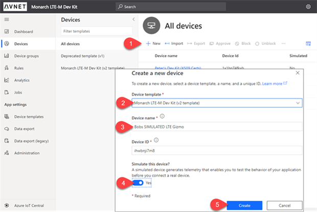
1) Go to the Devices section, then Click on +New to create a simulated device
2) In the form that opens, select the Avnet-provided Device Template
3) Specify a unique Device Name of your choice, then
4) Select Yes for Simulate the Device?
5) Click on the blue Create button
6) After a couple of seconds the new device will show-up as a simulated device under the listed devices
7) Click on this new device, select Overview and then wait for the simulated telemetry to start appearing on the dashboard…
Tip: Screenshots from here onwards show use of the “dark theme” display mode recommended earlier

8) Next, select the Raw Data view, to inspect the simulated incoming telemetry messages

9) Click on one of the telemetry messages to inspect it’s contents
A vertical listing of all the telemetry fields will display
A horizontal listing of the modeled data fields can be scrolled through using the arrow keys
(When this view is used later for inspecting telemetry from a real device, any received telemetry that is not yet modeled in the dashboard, will get displayed as JSON text)
Register and Configure a “Real Device” in IoT Central
1) As done with simulated device, from the Devices section, click on +New to create a device
2) Complete the form as before, using a new Device Name.
3) This time select No Select Yes for Simulate the Device?
4) The new device will show-up as a non-simulated device under the listed devices
5. Setup Verizon ThingSpace IoT Dataplan
Before making edits and building the MCU application, it is recommended that you complete the set-up of your Verizon ThingSpace IoT dataplan.
1) Go to https://thingspace.verizon.com/iot-marketplace/ where you will need to complete these steps:
a) Select a connectivity plan (choose one of the six listed monthly plans)
b) Sign-up for a Developer Connectivity Account and pay for selected plan with a credit card
c) Activate your Verizon-certified Monarch LTE-M device

2) Use the ICCID and IMEI details from the label on your Monarch Go modem when activating this device in your ThingSpace account
6. Configure the MCU Device Application
Set the Build Configuration to target Azure
It is critically important that the active build configuration be set correctly!
Right-click on the project name and set this as shown below…

Configure the Endpoint and Client Credentials using Shared Access Signature (SAS)
1) In your MCU application, navigate to msft_Azure_IoT\demo section then open the
msft_Azure_IoT_clientcredential.h header file

2) Edit line #22, adding the Azure DPS provisioning service as the MQTT Broker Endpoint
"global.azure-devices-provisioning.net"
3) In your Azure IoT Central application, select your real device,
then click on Connect to open the Device Connection dialog.


4) Copy the Scope ID (ID Scope) and Device ID values to the header file
#define clientcredentialAZURE_MQTT_BROKER_ENDPOINT "global.azure-devices-provisioning.net"
#define clientcredentialAZURE_IOT_SCOPE_ID ""
#define clientcredentialAZURE_IOT_DEVICE_ID ""
5) This application also includes some code to support the simpler Shared Access Signature (SAS) authentication. This requires SAS Primary Key for connecting your real device also needs to be added. While still in this Device Connection window, click on Shared Access Signature (SAS) then copy to the clipboard the Primary key that is displayed…
6) Back in MCUXpresso, under the msft_Azure_IoT\demo section that you accessed before, open msft_Azure_IoT_clientcredential_keys.h and edit line 14, adding the SAS Primary Key that you have just copied from the Azure IoT Central application
#define keyDEVICE_SAS_PRIMARY_KEY ""
8) Save after checking the edits you made in msft_Azure_IoT_clientcredential_keys.h
Configure the Geo Location Coordinates for your Device
Until Verizon ThingSpace Location API support is added (or a GPS enabled version of the Monarch Go modem is used), the device location will need to be hard-coded into the application in order for the IOTC dashboard map tile to correctly display the device location
9) One level-up under the msft_Azure_IoT section, now open msft_Azure_IoT.c
Look for the section of code where the location telemetry message is defined:
#define Device_Location_Telemetry_JSON
A couple of lines after this you will see where lat and lon are initialized with default values
double lat = 33.42745;
double lon = -111.98213;
Customize these values to the device location that you want mapped on your dashboard
Tip: An easy way to determine coordinates for any location is by examining it’s address in Google maps. eg. the coordinates shown above (for Avnet in Phoenix)

10) Save your edits to msft_Azure_IoT.c
8. Build and Download the MCU Application
Connect the USB cable from the Debug microUSB connector on the LPC55S69-EVK board, to your development computer, then build and download using the Debug icon in the IDE’s Quickstart panel…

8. Dashboard Visualization of Telemetry and Property Data
Overview Dashboard View
Click on the Overview tab to access this dashboard view
As you did previously with the simulated device, examine the Overview followed by the Raw Data views. Telemetry data will start appearing in these views a couple of seconds after starting the debugger

Notes:
Functionality underlying some of the following dashboard widgets has not yet been implemented in the initial release of the embedded application. In these cases, simulation telemetry or constant values are sent in their telemetry data fields (eg. Light Sensor, Current and Button-Press).
The map tile at present displays the location defined by coordinates in the embedded code, but in later release this will be replaced by location data supplied by the Verizon ThingSpace Location API)
Update rate for the dashboard visualization is around once every 10 seconds
Update rate for the telemetry transmission is initially at 1 minute (set to PT0H0M10S in ISO8601 notation)
(Telemetry Interval is reported in the About dashboard view)
The Telemetry Interval default setting is defined at compile time in the MCU software.
To change this, edit Hours, Minutes, Seconds values of the Device_Control_Property_JSON setting, under case AZURE_SM_PUB_SET_CONTROL_PROPERTIES section in the msft_Azure_IoT.c file.
(Future software releases will support a text box accessible from the Settings dashboard view, to allow remote adjustment of the Telemetry Interval by the user)
In top-right corner of all tiles is a clickable ßà maximize symbol (Esc to return to normal view).
Raw Data Dashboard View
Click on the Raw Data tab to access this dashboard view
Open-up some of the messages in the Raw Data view. This will reveal the different types of messages that are being communicated between the Monarch LTE-M Dev Kit and the Azure cloud service
eg.

About Dashboard View
Click on the About tab to access this dashboard view
This reports static Device Information properties from the Dev Kit, as well as providing a passive view of the control settings that the dashboard has sent to the Dev Kit

Tip: Images displayed at lower edge of this window are clickable links which are best accessed using mouse right-click then “Open link in new window” (rather than lose presently selected dashboard view)

Help Info Dashboard View
Click on the Help Info tab to access this dashboard view
This view is informational only. It provides an example of how to embed sales and support information for operator (or customer) access while using your cloud-based IoT Central application

Work-around Required!
An issue encountered with export of the application template, requires that custom tiles containing images need to be edited (the image re-entered) in the version of template with which you are developing your cloud-based IoT Central application. This is simple to do and also provides opportunity for the developer to replace images and further customize their dashboards (This is discussed in more detail on next page)
Procedure to Replace a Tile Image Missing from Template
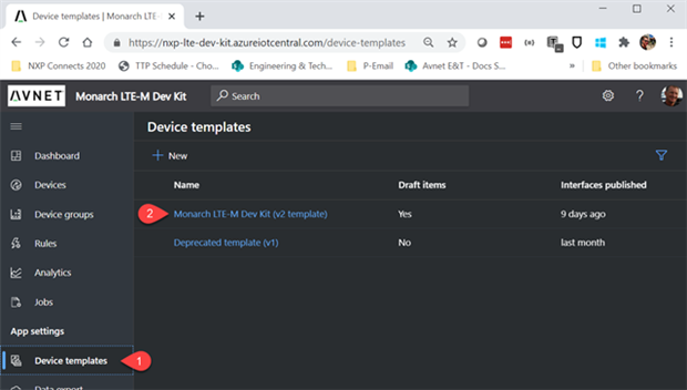
1) From the navigation sidebar, open the Device Templates view
2) Select the Monarch LTE-M Dev Kit (v2 template)
Procedure steps below, refer to the screenshot on next page:
3) Rename the template to a name of your choice (this auto-saves when you move to a different field)
4) Under Views, select the dashboard view that you wish to edit.
For this example select the About dashboard view
5) Click on the settings icon in one of the custom tiles that does not display it’s image correctly
6) This will open a “Configure Image” panel.
Change the title of this tile (in dashboard use, the title is visible when mouse hovers over the tile)
7) Re-enter or replace the image used in this tile, by clicking on the Image field and then browsing to the image that needs to be inserted.
You can also edit the URL that a mouse-click on this image will link to, by editing the URL field
8) Click on Update (to save the Tile edits)
9) Click on Save (to save the View edits)
10)For this updated template to be deployed you need to “publish” it.
When finished with all edits and the updated tiles and views have been saved, click on “publish” at top of the template window


9. Dashboard Control of the Dev Kit Hardware
Settings Dashboard View
Three slider switches are provided for remotely controlling the RGB LEDs on the Dev Kit hardware.
Note that the Save button at top of this view must be clicked to transmit the changes that you make to these slider switches!

Command Dashboard View
Not currently supported by the MCU application, but the intention of this control is to support remote reboot of the Dev Kit application.

10. Use of Verizon ThingSpace Location Service APIs
This will be supported in the next release of this reference design. More information on this topic can be accessed on the Verizon ThingSpace webpages.
11. Software Customization / Use of other Cloud Services
The intention of this application is to show what is possible, using NXP’s versatile low-power LPC55 series microcontrollers, Sequans Monarch Go LTE-M modem connectivity, Verizon’s ThingSpace connectivity plans and service APIs, plus Microsoft’s IoT Central cloud service.
As tabled on page 5 of this document, it is possible to reconfigure the embedded application to instead target the Amazon AWS cloud service. This build configuration supports a subset of telemetry functionality and different user interfaces (Alexa voice I/O, plus touchscreen UI via an Android smartphone App).

12. Hardware Expansion via Click Shuttle Interface
Support for MikroE Click boards is provided via an optional MikroE Shuttle Adapter. This inexpensive adapter ($8.00, p/n: MIKROE-2880) when attached to the Monarch LTE-M Shield, facilitates the use of MikroE Click boards from more than 900 different Click boards now available.
See the following webpages for more information (Avnet also stocks the MikroE boards)
https://www.mikroe.com/mikrobus-shuttle
https://www.mikroe.com/mikrobus-shuttle-5pcs

13. Hardware Expansion via Pmod Interface
Support for Pmod peripheral boards from Digilent as well as from 3rd-party suppliers is also possible via the Pmod connector on the LPC55S69-EVK board. eg.
https://store.digilentinc.com/pmod-expansion-modules/pmod-boards/
https://www.maximintegrated.com/en/products/evkits/fpga-modules/index.cfm
https://www.te.com/usa-en/search.html?q=Pmod&source=header
14. NXP MCU and SE050 Secure Element Security Features
The Monarch LTE-M Development Kit provides an extensive range of security features on the:
- NXP LPC55S69 Microcontroller, and the
- NXP SE050 Secure Element device (that is present on the Avnet Monarch LTE-M Shield)
Lookout for an upcoming Avnet Application Note on this topic!
Appendix: Installation of NXP Tools (SDK and IDE)
Install LPCXpresso55S69 SDK (v2.8.x or later)
1. Open a web browser and navigate to the MCUXpresso homepage mcuxpresso.nxp.com
2. Click on Select Development Board to download the LPCXpresso55S69 SDK with AWS component

3. After being redirected to the nxp.com login page, enter your NXP account login info (or register for a new account)
4. Back on the Select Development Board page, search for LPCXpresso55S69,
Select it then click on Build MCUXpresso SDK

5. At Select Optional Middleware section, click the + Add software component, a window will pop-up with a list of components, Select All then click Save Changes

6. Select Download SDK
Note: You may see “Request to Build” instead, if this the case, then click on that.
7. After the package gets built, there will be a new download in the SDK Dashboard section.
Click on the “Download SDK archive and documentation” button.

Install MCUXpresso IDE (11.2.x or later)
8. Open mcuxpresso.nxp.com
9. Select the Software and Tools tab, then
click Learn More about MCUXpresso IDE

10. Download and install the MCUXpresso IDE (11.2.x version or later)
Top Comments