element14 Community
element14 Community
    Register Log In
  • Site
  • Search
  • Log In Register
  • Community Hub
    Community Hub
    • What's New on element14
    • Feedback and Support
    • Benefits of Membership
    • Personal Blogs
    • Members Area
    • Achievement Levels
  • Learn
    Learn
    • Ask an Expert
    • eBooks
    • element14 presents
    • Learning Center
    • Tech Spotlight
    • STEM Academy
    • Webinars, Training and Events
    • Learning Groups
  • Technologies
    Technologies
    • 3D Printing
    • FPGA
    • Industrial Automation
    • Internet of Things
    • Power & Energy
    • Sensors
    • Technology Groups
  • Challenges & Projects
    Challenges & Projects
    • Design Challenges
    • element14 presents Projects
    • Project14
    • Arduino Projects
    • Raspberry Pi Projects
    • Project Groups
  • Products
    Products
    • Arduino
    • Avnet Boards Community
    • Dev Tools
    • Manufacturers
    • Multicomp Pro
    • Product Groups
    • Raspberry Pi
    • RoadTests & Reviews
  • Store
    Store
    • Visit Your Store
    • Choose another store...
      • Europe
      •  Austria (German)
      •  Belgium (Dutch, French)
      •  Bulgaria (Bulgarian)
      •  Czech Republic (Czech)
      •  Denmark (Danish)
      •  Estonia (Estonian)
      •  Finland (Finnish)
      •  France (French)
      •  Germany (German)
      •  Hungary (Hungarian)
      •  Ireland
      •  Israel
      •  Italy (Italian)
      •  Latvia (Latvian)
      •  
      •  Lithuania (Lithuanian)
      •  Netherlands (Dutch)
      •  Norway (Norwegian)
      •  Poland (Polish)
      •  Portugal (Portuguese)
      •  Romania (Romanian)
      •  Russia (Russian)
      •  Slovakia (Slovak)
      •  Slovenia (Slovenian)
      •  Spain (Spanish)
      •  Sweden (Swedish)
      •  Switzerland(German, French)
      •  Turkey (Turkish)
      •  United Kingdom
      • Asia Pacific
      •  Australia
      •  China
      •  Hong Kong
      •  India
      •  Korea (Korean)
      •  Malaysia
      •  New Zealand
      •  Philippines
      •  Singapore
      •  Taiwan
      •  Thailand (Thai)
      • Americas
      •  Brazil (Portuguese)
      •  Canada
      •  Mexico (Spanish)
      •  United States
      Can't find the country/region you're looking for? Visit our export site or find a local distributor.
  • Translate
  • Profile
  • Settings
GIZMO 2
  • Products
  • Dev Tools
  • Single-Board Computers
  • GIZMO 2
  • More
  • Cancel
GIZMO 2
Blog GIZMO 2 another 3D printed enclosure
  • Blog
  • Forum
  • Documents
  • Files
  • Members
  • Mentions
  • Sub-Groups
  • Tags
  • More
  • Cancel
  • New
Join GIZMO 2 to participate - click to join for free!
  • Share
  • More
  • Cancel
Group Actions
  • Group RSS
  • More
  • Cancel
Engagement
  • Author Author: bwelsby
  • Date Created: 31 Jan 2015 12:43 AM Date Created
  • Views 3672 views
  • Likes 8 likes
  • Comments 20 comments
  • sbc
  • single_board_computer
  • gizmo2
  • gizmosphere
  • 3d_printed
Related
Recommended

GIZMO 2 another 3D printed enclosure

bwelsby
bwelsby
31 Jan 2015

     This is my design for a 3D printed enclosure, I have used OpenSCAD for this as it's my preferred design tool and just for fun I used the GIZMO2 as my development workstation.

To start with I set-up my GIZMO2 with a 120GB SSD and installed Lubuntu, this is Ubuntu but with a lightweight GUI so requires less memory.  I then installed OpenSCAD with a simple


sudo apt-get install openscad


If anyone would like the full details for installing Lubuntu on SSD let me know and I will post them.

Also just for fun I configured an email client so I didn't need to use another machine at the same time, indeed I am also writing this using the GIZMO2 with the Firefox web browser.


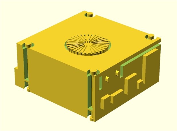
Here is an exploded view of all the parts for the final design,

image


As you can see the enclosure has three main parts, the base, middle, and top. there is also a small cover for the expansion ports and two small buttons for Power and Reset.

The GIZMO2 PCB is sandwiched between the base and middle parts.  M3 or similar sized self tapping  screws fasten everything together, The expansion port cover has ventilation slots and is a snug fit so is just pushed into place.

You can just use the base part on it's own if you wish to have full access to all the PCB buttons, LEDs connectors etc.


The design process.

     I started off by measuring the PCB and position of all the connectors. I then used these to create a model to represent all the space and openings withing the enclosure itself. I then designed a solid block and subtracted this model from it to create the final enclosure.  For printing I then split this into the three pieces required. The expansion cover and buttons are separate designs,


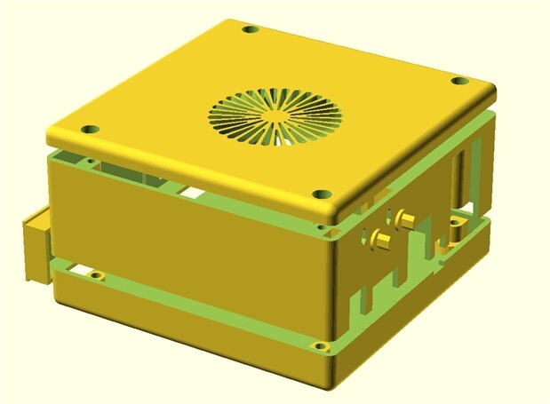
Here is what the internal space model looks like:

image

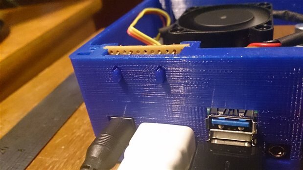
The radial structures on the top create the fan vent holes. I also added structures to hold a small piece of stripboard holding the two push buttons but you can't see them as they are inside this model.you can see this in photos below.


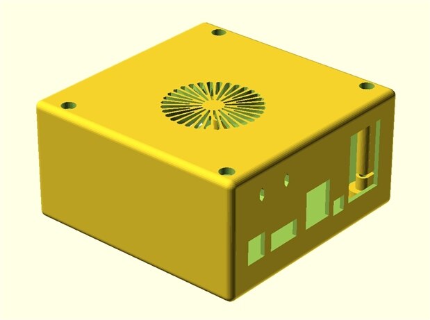
and when you subtract this from a sold block you get this

image

Full OpenSCAD source code is attached, it's actually a text file so you don't need OpenSCAD to view it. all dimensions are in millimeters. if you don't understand any of it just ask.

Ok now for the photos


image


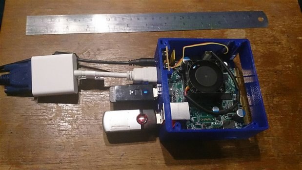
The large white adapter is a Pi-View HDMI to VGA

The USB dongle in the middle is a wifi adapter and the one at the bottom is for  USB wireless  keyboard and mouse


Here is a close-up of the power and reset buttons, maybe I should print them in another colour to make them stand out image

image

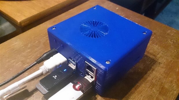
And one with the top on

image

STOP PRESS

I just got to this part of the blog when cstanton  posted that the underside of the PCB should have some ventilation although I haven't had any problems and nothing feels too hot to the touch,  I have updated the attached sources to add some holes in the base, these are not shown in the photos and design images above. I will also add some small rubber feet to the bottom too. The airflow from the fan should exit via the slots in the expansion cover, if needed then some slots can be added to the side panels of the middle part.. This is where a thermal imaging camera would come in handy...  not got one though image


So why print it in blue...  hmmm     well it is my favorite colour image  but that's not the reason, it just so happens that I managed to get a great deal but they only had blue and so it's the cheapest filament I have, it prints fine and is ideal for prototype work. Once I am happy with the end product I can use other, more expensive and better quality filament in various colours.

My printer is a RepRapPro tricolour mendel which I have modified quite a bit, I have printed these with a 0.3mm nozzle and 0.2mm layer height. My print bed is heated glass with a thin coating of UHU glue stick 55 Deg bed temp 205 Deg nozzle temp for PLA.


Well there you have it,  All comments, criticisms and suggestions welcome.


EDIT: Here is the underside view with the added ventilation...  maybe a little OTT image

image

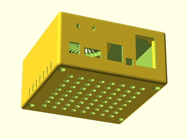
Edit 06-April-2015 :-

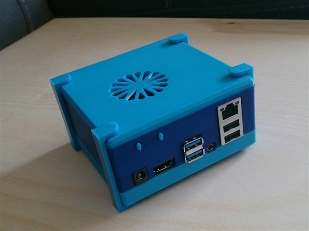
I have made a couple of changes, increased size of fan vents and added some clips that go over screw holes an act as stands.

image

Attachments:
gizmo2boxV1.0_30-Jan-2015.scad.zip
Gizmo2BoxV1.1_01-Feb-2015.zip
  • Sign in to reply

Top Comments

  • fvan
    fvan over 10 years ago +2
    Looks great!
  • Former Member
    Former Member over 10 years ago in reply to bwelsby +2
    Perfect! Thanks so much for the great design and help! It's printing now, Adam White
  • Former Member
    Former Member over 10 years ago in reply to Former Member +2
    I did a little remix: removed the pci port hole, don't use that currently additional side vents on middle part, I encountered that the air flow could not really exit the case because of missing holes in…
  • balearicdynamics
    balearicdynamics over 9 years ago in reply to bwelsby

    Hi Brian, as a matter of fact yes, it is very useful just for the already well done job. Then I should make the box a bit higher and longer as the back connector should remain inside and are connected to a board showing the health status of the Gizmo2 and other features (powering, extra fan PWM management and more). I will start soon posting the features of the Gizmo2 server I am building on Element14.


    Enrico

    • Cancel
    • Vote Up 0 Vote Down
    • Sign in to reply
    • More
    • Cancel
  • bwelsby
    bwelsby over 9 years ago in reply to balearicdynamics

    Hi Enrico,

    I chose one corner as a reference point, then used digital calpers and ruler to measure the points. I then added a little extra to give clearance for the connectors. I then made some test prints to make final corrections.

    I hope it is useful to you and look forward to seeing your designs.

    Brian

    • Cancel
    • Vote Up 0 Vote Down
    • Sign in to reply
    • More
    • Cancel
  • balearicdynamics
    balearicdynamics over 9 years ago

    Very good job Brian!


    I will start from this design with some changes for a more complete Gizmo2 management, that I will post further. I have a question that made me crazy just in these days; How did you measures correctly the occupied space of the connectors ? I have tried with caliber and ruler but I was never sure of the dimensions. To be honest, I have - lucky - found your post just searching for something showing the correct dimensions  of the board connectors image


    Thank you for your effort. Enrico

    • Cancel
    • Vote Up 0 Vote Down
    • Sign in to reply
    • More
    • Cancel
  • bwelsby
    bwelsby over 10 years ago in reply to Former Member

    Looks great, will check it out.


    Brian

    • Cancel
    • Vote Up +1 Vote Down
    • Sign in to reply
    • More
    • Cancel
  • Former Member
    Former Member over 10 years ago in reply to Former Member

    I did a little remix:

    • removed the pci port hole, don't use that currently
    • additional side vents on middle part, I encountered that the air flow could not really exit the case because of missing holes in the middle part after removing the pci hole
    • buttons on the opposite side, which I name as "front", cables at the back image
    • less fancy classical top fan cover

    If you are interested:

    https://gist.github.com/megglos/ee370e46f64f490cc111


    image

    image

    • Cancel
    • Vote Up +2 Vote Down
    • Sign in to reply
    • More
    • Cancel
>
element14 Community

element14 is the first online community specifically for engineers. Connect with your peers and get expert answers to your questions.

  • Members
  • Learn
  • Technologies
  • Challenges & Projects
  • Products
  • Store
  • About Us
  • Feedback & Support
  • FAQs
  • Terms of Use
  • Privacy Policy
  • Legal and Copyright Notices
  • Sitemap
  • Cookies

An Avnet Company © 2025 Premier Farnell Limited. All Rights Reserved.

Premier Farnell Ltd, registered in England and Wales (no 00876412), registered office: Farnell House, Forge Lane, Leeds LS12 2NE.

ICP 备案号 10220084.

Follow element14

  • X
  • Facebook
  • linkedin
  • YouTube