element14 Community
element14 Community
    Register Log In
  • Site
  • Search
  • Log In Register
  • About Us
  • Community Hub
    Community Hub
    • What's New on element14
    • Feedback and Support
    • Benefits of Membership
    • Personal Blogs
    • Members Area
    • Achievement Levels
  • Learn
    Learn
    • Ask an Expert
    • eBooks
    • element14 presents
    • Learning Center
    • Tech Spotlight
    • STEM Academy
    • Webinars, Training and Events
    • Learning Groups
  • Technologies
    Technologies
    • 3D Printing
    • FPGA
    • Industrial Automation
    • Internet of Things
    • Power & Energy
    • Sensors
    • Technology Groups
  • Challenges & Projects
    Challenges & Projects
    • Design Challenges
    • element14 presents Projects
    • Project14
    • Arduino Projects
    • Raspberry Pi Projects
    • Project Groups
  • Products
    Products
    • Arduino
    • Avnet Boards Community
    • Dev Tools
    • Manufacturers
    • Multicomp Pro
    • Product Groups
    • Raspberry Pi
    • RoadTests & Reviews
  • Store
    Store
    • Visit Your Store
    • Choose another store...
      • Europe
      •  Austria (German)
      •  Belgium (Dutch, French)
      •  Bulgaria (Bulgarian)
      •  Czech Republic (Czech)
      •  Denmark (Danish)
      •  Estonia (Estonian)
      •  Finland (Finnish)
      •  France (French)
      •  Germany (German)
      •  Hungary (Hungarian)
      •  Ireland
      •  Israel
      •  Italy (Italian)
      •  Latvia (Latvian)
      •  
      •  Lithuania (Lithuanian)
      •  Netherlands (Dutch)
      •  Norway (Norwegian)
      •  Poland (Polish)
      •  Portugal (Portuguese)
      •  Romania (Romanian)
      •  Russia (Russian)
      •  Slovakia (Slovak)
      •  Slovenia (Slovenian)
      •  Spain (Spanish)
      •  Sweden (Swedish)
      •  Switzerland(German, French)
      •  Turkey (Turkish)
      •  United Kingdom
      • Asia Pacific
      •  Australia
      •  China
      •  Hong Kong
      •  India
      •  Korea (Korean)
      •  Malaysia
      •  New Zealand
      •  Philippines
      •  Singapore
      •  Taiwan
      •  Thailand (Thai)
      • Americas
      •  Brazil (Portuguese)
      •  Canada
      •  Mexico (Spanish)
      •  United States
      Can't find the country/region you're looking for? Visit our export site or find a local distributor.
  • Translate
  • Profile
  • Settings
GIZMO 2
  • Products
  • Dev Tools
  • Single-Board Computers
  • GIZMO 2
  • More
  • Cancel
GIZMO 2
Forum Gimzo 2 custom On/Off button?
  • Blog
  • Forum
  • Documents
  • Files
  • Members
  • Mentions
  • Sub-Groups
  • Tags
  • More
  • Cancel
  • New
Join GIZMO 2 to participate - click to join for free!
Actions
  • Share
  • More
  • Cancel
Forum Thread Details
  • State Suggested Answer
  • Replies 51 replies
  • Answers 2 answers
  • Subscribers 13 subscribers
  • Views 6119 views
  • Users 0 members are here
Related

Gimzo 2 custom On/Off button?

Former Member
Former Member over 10 years ago

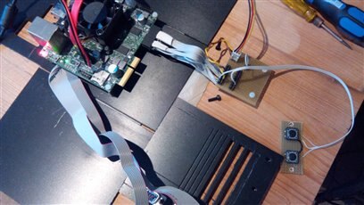
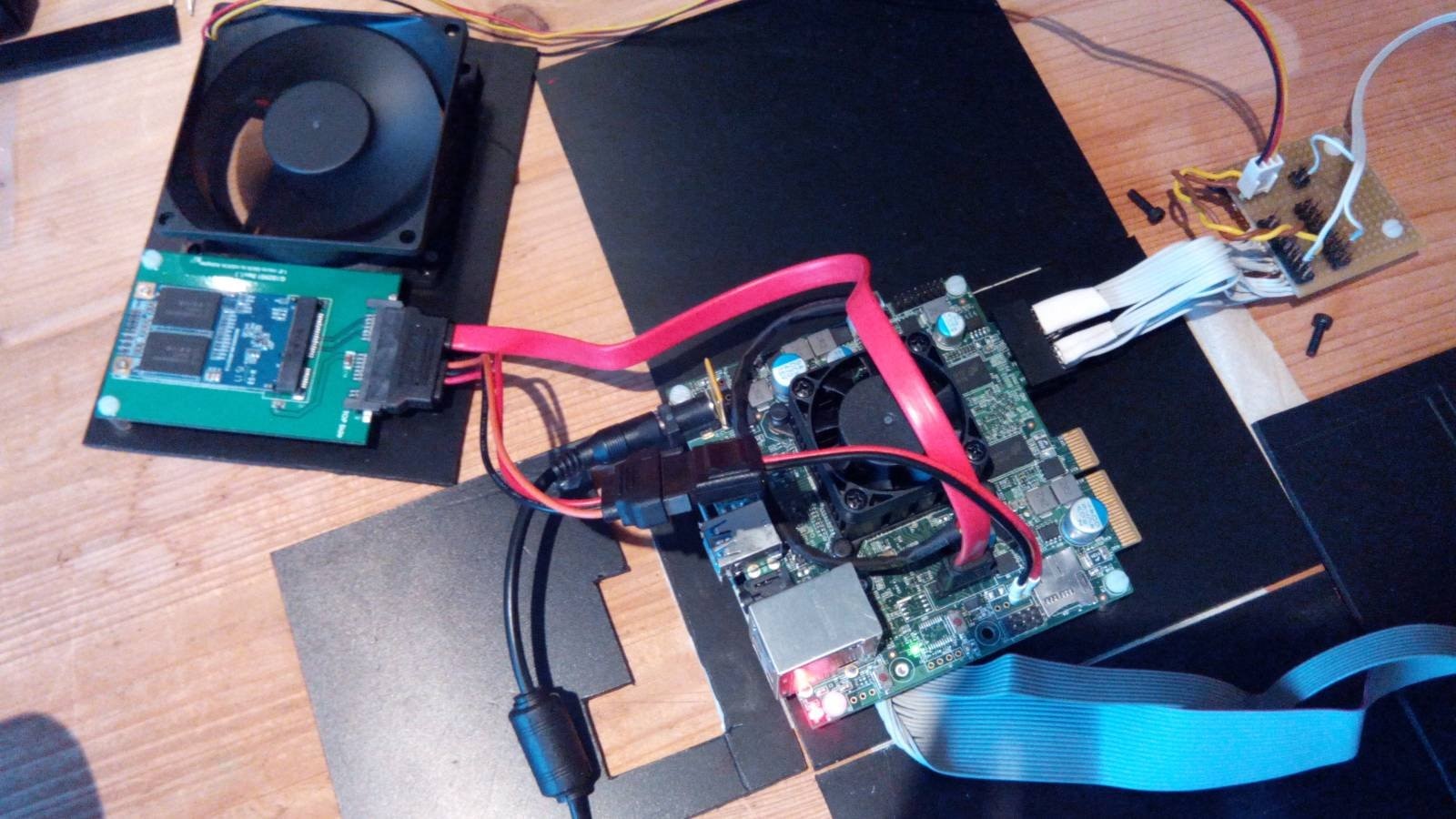
Ideally I'd want to modify the BIOS to autostart without pressing any button. But if nobody ends up knowing how to do that, I'd like to at least have a custom proper button on my device's case for turning the Gizmo on. I've read one of the pin pairs can be used, but which ones?


mCPawjq.png

  • Sign in to reply
  • Cancel

Top Replies

  • shabaz
    shabaz over 10 years ago +1 suggested
    Hi Mark, The information is in this thread: http://www.element14.com/community/community/designcenter/single-board-computers/gizmo2/blog/2015/07/30/gizmo2--flash-bios-to-autostart-on-power-up . In summary…
  • shabaz
    shabaz over 10 years ago in reply to Former Member +1
    Hi Mark, Enrico is suggesting try it with a resistor, see if it works for you. If you observe some behavior that is undesirable (e.g. having to hold the button pressed for a long time) then it can be considered…
  • shabaz
    0 shabaz over 10 years ago

    Hi Mark,


    The information is in this thread: http://www.element14.com/community/community/designcenter/single-board-computers/gizmo2/blog/2015/07/30/gizmo2--flash-bios-to-autostart-on-power-up .

    In summary you can either solder your custom switch directly across the switch on the circuit board (not ideal) or access the same connections on a PCIe connector or use the debug connector which

    is probably easiest (this is all in the schematic PDF doc).

    You can see in the PDF in the page 3 block diagram that the power button circuit is on page 21 in the PDF, and that the relevant signal is called PWR_BTN and that it is connects to ground via a 10 ohm resistor.

    So you'll need an external switch and a 10 ohm resistor in series.

    By doing Ctrl-F and searching for the text 'PWR_BTN' in the PDF, you'll see that the signal is brought out to the debug connector marked J13, pin 10.

    You can use pin 15 as the ground end of the switch. Pin 1 of the debug connector will be indicated with a square shaped pad, and the pin numbering is in a zig-zag fashion as shown in the

    schematic (I don't have a Gizmo2 near me to confirm with a multimeter, but you could easily confirm by putting one end on pin 10, and the other at the power button on the board, and you should measure

    10 ohms resistance.

    • Cancel
    • Vote Up +1 Vote Down
    • Sign in to reply
    • Verify Answer
    • Reject Answer
    • Cancel
  • Former Member
    0 Former Member over 10 years ago in reply to shabaz

    I'm more a programmer and the schematics are a bit confusing. I understood the part about connecting a button and 10 Ohm resistor in series, but not which pin to which pin (yes I prefer the pins over soldering on the PCIe or across the stock button).

    Sorry. I didn't expect to do have to do any hardware mods for something this trivial, but luckily it seems the only hardware modification I'll be doing.

    • Cancel
    • Vote Up 0 Vote Down
    • Sign in to reply
    • Verify Answer
    • Cancel
  • fvan
    0 fvan over 10 years ago

    Check out this post where I added an external power and reset button: http://www.element14.com/community/community/designcenter/single-board-computers/gizmo2/blog/2015/01/28/gizmo2-adding-external-pwr-and-rst-buttons

    • Cancel
    • Vote Up 0 Vote Down
    • Sign in to reply
    • Verify Answer
    • Reject Answer
    • Cancel
  • Former Member
    0 Former Member over 10 years ago in reply to fvan

    Oh wow, so much great tutorials I'm having hard time finding image


    So you didn't use a resistor?

    Is there any requirement for what button can be used. All I know is buttons have a maximum current rating, this shows how little my electronics knowledge is. But it's going to be fun programming the Gizmo after I get this figured out.


    PS. Is that a 3d printed enclosure? That's another hobby of mine.

    • Cancel
    • Vote Up 0 Vote Down
    • Sign in to reply
    • Verify Answer
    • Cancel
  • fvan
    0 fvan over 10 years ago in reply to Former Member

    Yes,


    mine is here: http://www.element14.com/community/community/designcenter/single-board-computers/gizmo2/blog/2015/01/26/gizmo2-3d-printable-enclosure


    and Brian made an even better one: http://www.element14.com/community/community/designcenter/single-board-computers/gizmo2/blog/2015/01/31/gizmo-2-another-3d-printed-enclosure

    • Cancel
    • Vote Up 0 Vote Down
    • Sign in to reply
    • Verify Answer
    • Cancel
  • balearicdynamics
    0 balearicdynamics over 10 years ago

    Just a preview I am working on and will be open and posted soon (maybe in a week or two):


    Gizmo2 + internal SSD + External HDD with secondary SATA and 5V SATA Power, external power, power-on and reset buttons and something more. Honestly, this project has not only been inspired by the post of fvan but his post confirmed me some of my doubts and made this possible. Coming soon image


    Enrico

    imageimage

    image

    • Cancel
    • Vote Up 0 Vote Down
    • Sign in to reply
    • Verify Answer
    • Cancel
  • Former Member
    0 Former Member over 10 years ago in reply to fvan

    Nice.


    About the connection to the pins though, you didnt need a resistor?

    • Cancel
    • Vote Up 0 Vote Down
    • Sign in to reply
    • Verify Answer
    • Cancel
  • shabaz
    0 shabaz over 10 years ago in reply to Former Member

    Hi Mark,


    It is your choice. It will function either way. Personally I would use it, because no components are perfect and it will look after your switch (provides a current limit - those small board switches might not handle much current), provides a bit of debounce (not that it should matter for a power-on circuit but anyway..)  (EDIT - also provides some protection if you accidentally connect the wire to an incorrect supply wire accidentally) - plus the original designers used it, so even if we cannot see their purpose it is harmless to add it.

    But equally a body of engineers would just omit the resistor - there is not a lot of energy stored in that bit of circuit for example. So if it were a courtroom it would be a hung jury ; )

    You can use any switch you like for the purposes of this button function, as long as it is a normally-open switch.

    • Cancel
    • Vote Up 0 Vote Down
    • Sign in to reply
    • Verify Answer
    • Cancel
  • balearicdynamics
    0 balearicdynamics over 10 years ago in reply to Former Member

    No, I have not used the resistor with a reason (not sure it is correct). Seeing in the scheme just as has suggested Shabaz in his post, my though is the following: If I should manage a push button with a GPIO port it is correct to use a resistor and eventually also a capacitor, just as the circuit in the scheme of these two buttons. But in this case the push button sends to GND exactly the signal pin "reset" and "system power" that - in the same Gizmo2 scheme - it is shown with a resistor capacitor etc. So I have excluded to add one more.


    Pay attention as it is not sure that I am right image


    Enrico

    • Cancel
    • Vote Up 0 Vote Down
    • Sign in to reply
    • Verify Answer
    • Cancel
  • Former Member
    0 Former Member over 10 years ago in reply to balearicdynamics

    If I should manage a push button with a GPIO port it is correct to use a resistor and eventually also a capacitor, just as the circuit in the scheme of these two buttons. But in this case the push button sends to GND exactly the signal pin "reset" and "system power" that - in the same Gizmo2 scheme - it is shown with a resistor capacitor etc. So I have excluded to add one more.


    Not sure I understand.


    For the record I don't mind using a resistor, it's a <$1 difference, I just wanted to test out right now if it works with my switch.

    • Cancel
    • Vote Up 0 Vote Down
    • Sign in to reply
    • Verify Answer
    • Cancel
>
element14 Community

element14 is the first online community specifically for engineers. Connect with your peers and get expert answers to your questions.

  • Members
  • Learn
  • Technologies
  • Challenges & Projects
  • Products
  • Store
  • About Us
  • Feedback & Support
  • FAQs
  • Terms of Use
  • Privacy Policy
  • Legal and Copyright Notices
  • Sitemap
  • Cookies

An Avnet Company © 2025 Premier Farnell Limited. All Rights Reserved.

Premier Farnell Ltd, registered in England and Wales (no 00876412), registered office: Farnell House, Forge Lane, Leeds LS12 2NE.

ICP 备案号 10220084.

Follow element14

  • X
  • Facebook
  • linkedin
  • YouTube