element14 Community
element14 Community
    Register Log In
  • Site
  • Search
  • Log In Register
  • Community Hub
    Community Hub
    • What's New on element14
    • Feedback and Support
    • Benefits of Membership
    • Personal Blogs
    • Members Area
    • Achievement Levels
  • Learn
    Learn
    • Ask an Expert
    • eBooks
    • element14 presents
    • Learning Center
    • Tech Spotlight
    • STEM Academy
    • Webinars, Training and Events
    • Learning Groups
  • Technologies
    Technologies
    • 3D Printing
    • FPGA
    • Industrial Automation
    • Internet of Things
    • Power & Energy
    • Sensors
    • Technology Groups
  • Challenges & Projects
    Challenges & Projects
    • Design Challenges
    • element14 presents Projects
    • Project14
    • Arduino Projects
    • Raspberry Pi Projects
    • Project Groups
  • Products
    Products
    • Arduino
    • Avnet & Tria Boards Community
    • Dev Tools
    • Manufacturers
    • Multicomp Pro
    • Product Groups
    • Raspberry Pi
    • RoadTests & Reviews
  • About Us
    About the element14 Community
  • Store
    Store
    • Visit Your Store
    • Choose another store...
      • Europe
      •  Austria (German)
      •  Belgium (Dutch, French)
      •  Bulgaria (Bulgarian)
      •  Czech Republic (Czech)
      •  Denmark (Danish)
      •  Estonia (Estonian)
      •  Finland (Finnish)
      •  France (French)
      •  Germany (German)
      •  Hungary (Hungarian)
      •  Ireland
      •  Israel
      •  Italy (Italian)
      •  Latvia (Latvian)
      •  
      •  Lithuania (Lithuanian)
      •  Netherlands (Dutch)
      •  Norway (Norwegian)
      •  Poland (Polish)
      •  Portugal (Portuguese)
      •  Romania (Romanian)
      •  Russia (Russian)
      •  Slovakia (Slovak)
      •  Slovenia (Slovenian)
      •  Spain (Spanish)
      •  Sweden (Swedish)
      •  Switzerland(German, French)
      •  Turkey (Turkish)
      •  United Kingdom
      • Asia Pacific
      •  Australia
      •  China
      •  Hong Kong
      •  India
      •  Japan
      •  Korea (Korean)
      •  Malaysia
      •  New Zealand
      •  Philippines
      •  Singapore
      •  Taiwan
      •  Thailand (Thai)
      •  Vietnam
      • Americas
      •  Brazil (Portuguese)
      •  Canada
      •  Mexico (Spanish)
      •  United States
      Can't find the country/region you're looking for? Visit our export site or find a local distributor.
  • Translate
  • Profile
  • Settings
BeagleBoard
  • Products
  • Dev Tools
  • Single-Board Computers
  • BeagleBoard
  • More
  • Cancel
BeagleBoard
Blog BBB - Building a DAC
  • Blog
  • Forum
  • Documents
  • Quiz
  • Polls
  • Files
  • Members
  • Mentions
  • Sub-Groups
  • Tags
  • More
  • Cancel
  • New
Join BeagleBoard to participate - click to join for free!
  • Share
  • More
  • Cancel
Group Actions
  • Group RSS
  • More
  • Cancel
Engagement
  • Author Author: shabaz
  • Date Created: 6 Jul 2013 7:19 PM Date Created
  • Views 16730 views
  • Likes 8 likes
  • Comments 126 comments
  • onsemi
  • audio
  • dac
  • bbb
  • texas_instruments
  • bb_black
  • beagle_bone_black
  • ti
Related
Recommended

BBB - Building a DAC

shabaz
shabaz
6 Jul 2013

Introduction

This project was about getting audio out of the BeagleBone Black. The aim was to have stereo audio, at least as good as an iPod. See further below for the circuit, and also a video showing it working.

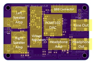
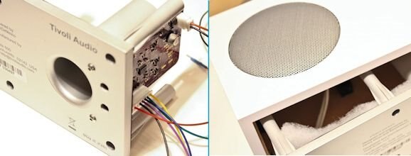
Later, this project was used to build a PCB design (see below for the link to this part 2, and then the PCB was used to make a home Sonos-type hi-fi audio player (see the link to part 3 below).


The BBB has an on-board I2S interface, which makes interfacing an external DAC easy. The I2S interface is connected from the AM3359 processor to the HDMI chip (TDA19988) but it is not required for HDMI to be used in order to make use of the I2S interface. The I2S interface is brought out to some pins on port P9 (see here for details). It was encouraging that Technoshaman and Donald Miller had some success with the interface, so I wanted to try it out and I got some time today.


Part 2 to this post, which implements the prototype, can be found by clicking here.
image

Part 3 implements a complete design in an enclosure for a Sonos-like solution.
image

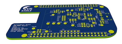
See Creating an Internet Radio for a complete project by the EAGLE team including board layouts
image


Parts Selection

Since the interface is capable of 24-bit/192kHz audio, it was worthwhile picking a nice DAC. A good but not over-the-top device seemed to be the Texas Instrument's PCM5101 which is nice because it has reasonable specs and also provides a built-in charge pump so that it can function from a single supply. A headphone amp was connected, and this was ON Semi's NCP2811A. The combination of PCM5101 (actually my prototype used PCM5101A which can also function from 1.8V, but this was not needed)  and NCP2811A was chosen so that the entire circuit could operate from the BBB supply if desired, even if it was from a Li-Ion battery that was powering the BBB, and for low noise and distortion. The only problem is that the PCM5101 has quite a high output (clearly a good thing!) but the audio amp minimum recommended gain is 1 and it cannot meet the required output voltage, and it means that it will distort at high volume. So, at a lower volume (and lower SNR) it will be fine, and I prefer this particular amp because of the very low distortion. The ON semi datasheet was sparse though.


Building It

This is the DAC prototype:
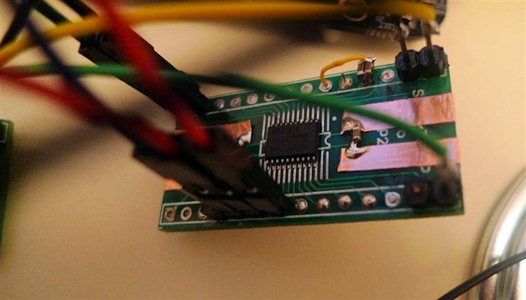
image

This is the whole thing connected up:
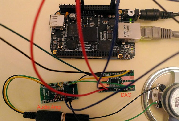
image

This is the rear of the board - a bit messier! It was built on a SMD to DIP adapter board with some copper tape for supply rails:
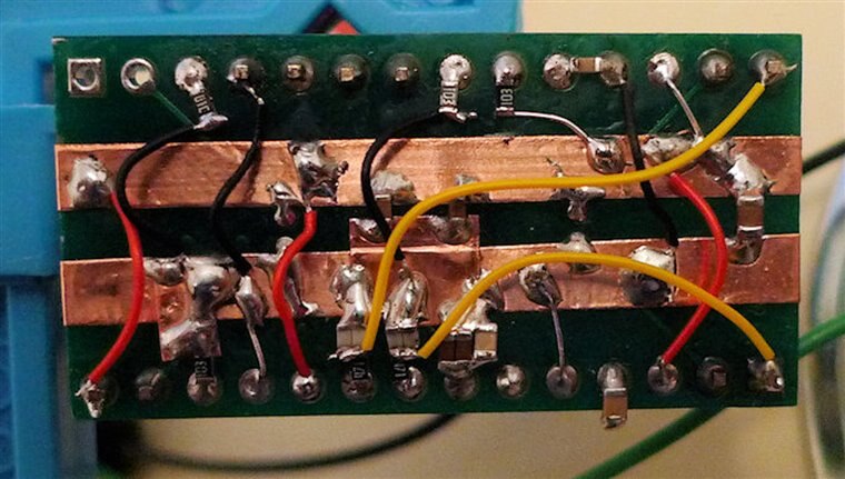
image

This is the audio amp - not a lot to it, since it is so integrated.
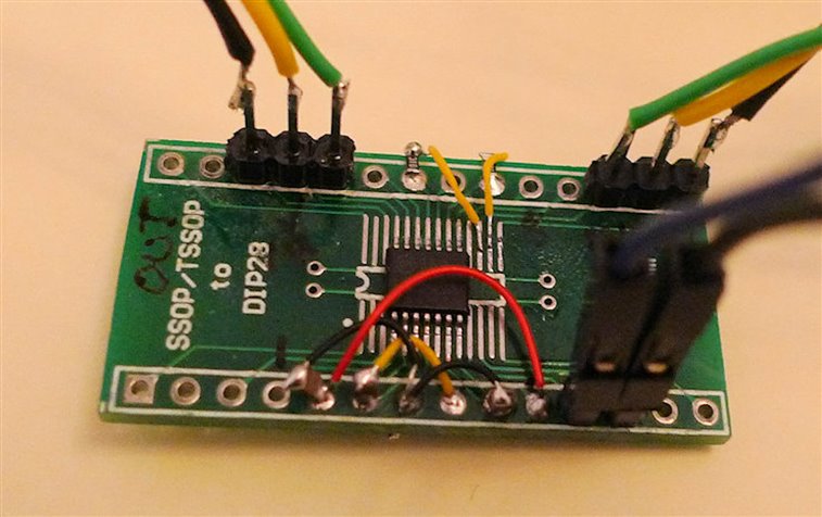
image


Testing It

I made a recording, but excuse the quality. The audio is from a small 64 ohm speaker picked up by a simple camera in-built microphone so it sounds bad, but connecting to headphones is a different story - it sounds as good as an ipod (although this is subjective - I don't have a way to measure). Another thing I still need to check is that originally I thought the data was read on the falling edge of the bitclock on the BBB, but I2S specifies the opposite. Maybe I made a mistake in my initial observations (I have not had a chance to re-check), or maybe it changed in a build. But the circuit as shown here works for me.


This is running on an not-recent Angstrom downloaded build (maybe a few weeks old image), and I still hear some very slight audio issues - it sounds like perhaps a break for a few tens of milliseconds occasionally, only if you're listening closely. I really hope it is resolved in a build soon (or maybe it is due to ffmpeg - perhaps avconv gives better results).

EDIT: I've since been using mplayer (command line is mplayer -ao alsa -volume 4 AmyWinehouse-BackToBlack.mp3  and either I'm not noticing any audio issues or they have disappeared). I've concluded it sounds at least as capable as my old ipod touch, maybe better).


I played audio using the command line:

ffmpeg -i AmyWinehouse-YouKnowImNoGood.mp3 -f alsa "default:CARD=Black" -re -vol 150

and it reported the stream as:

Stream #0.0: Audio: pcm_s16le, 44100 Hz, stereo, s16, 1411 kb/s


You don't have permission to edit metadata of this video.
Edit media
x
image
Upload Preview
image


Circuit Diagram

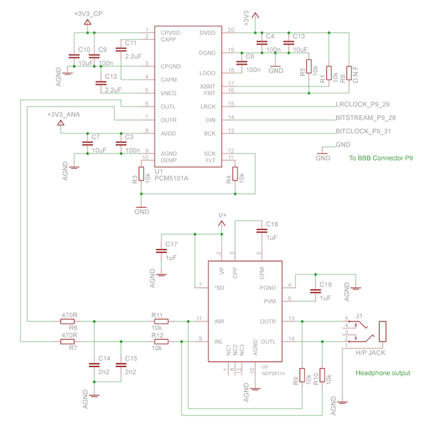
This is the circuit. All the 3.3V supplies were connected together for the prototype (I wouldn't do that for real, although it sounded very good in my limited tests). The amplifier V+ can be connected to 3.3V or the 5V supply (or the Li-Ion battery directly).

Note 16th Jan 2014: See the comments section below for more detail; the SCK pin on the PCM5101A was disconnected from 0V and instead connected to the BBB P9 pin 25. This will provide the lowest jitter by disabling the DAC's internal PLL. A sample capture of the audio quality (captured from the headphone output of the NCP2811A, just to give an approximate idea of what it sounds like from headphones) is attached to the post below, in the zip file dac-output.zip. More info on it in the comments section below.

Note 2: Please add a logic inverter to the bitclock connection. For more detail, see the comments below (search for the word 'bitclock' to make it easier to find). See the part 2 blog post, and the attached file there called dac-documentation.zip for the circuit diagram, showing the bitclock inversion. More recent BBB images may not need it, but it was certainly needed for the images I tested with.
image


Experiments with FLAC

I've also tried a FLAC file, but I'm hitting some limitation with ffmpeg it seems, and it picks a 16-bit format when it ought to be 24-bit. Meanwhile, avconv I couldn't get to work for MP3 or FLAC (it reported 'av_interleaved_write_frame(): Resource temporarily unavailable'). If anyone knows, any tips on how to play FLAC at 24-bit would be gratefully appreciated.


root@beaglebone:~# ffmpeg -i Taxman_2009_Digital_Remaster.flac -f alsa "default:CARD=Black" -re -vol 5
ffmpeg version v0.8.4, Copyright (c) 2000-2012 the Libav developers
  built on May 20 2013 13:00:42 with gcc 4.7.3 20130205 (prerelease)
This program is not developed anymore and is only provided for compatibility. Use avconv instead (see Changelog for the list of incompatible changes).
[flac @ 0x2da80] max_analyze_duration reached
Input #0, flac, from 'Taxman_2009_Digital_Remaster.flac':
  Metadata:
    ORIGREFERENCE   : 6C05C9F79EE74052A7991B9669B98533
    ORIGDATE        : 2009:09:14
    ORIGTIME        : 11:57:01
    TIMEREFERENCE   : 5292000
    CODINGHISTORY   : A=PCM,F=44100,W=24,M=stereo,T=SADiE5
    ORGANIZATION    : EMI
    TITLE           : Taxman
    track           : 1
    ARTIST          : The Beatles
    ALBUM           : Revolver (24 BIT Remastered)
    DATE            : 2009
  Duration: 00:02:37.85, bitrate: 1892 kb/s
    Stream #0.0: Audio: flac, 44100 Hz, 2 channels, s32
Incompatible sample format 's32' for codec 'pcm_s16le', auto-selecting format 's16'
Output #0, alsa, to 'default:CARD=Black':
  Metadata:
    ORIGREFERENCE   : 6C05C9F79EE74052A7991B9669B98533
    ORIGDATE        : 2009:09:14
    ORIGTIME        : 11:57:01
    TIMEREFERENCE   : 5292000
    CODINGHISTORY   : A=PCM,F=44100,W=24,M=stereo,T=SADiE5
    ORGANIZATION    : EMI
    TITLE           : Taxman
    track           : 1
    ARTIST          : The Beatles
    ALBUM           : Revolver (24 BIT Remastered)
    DATE            : 2009
    encoder         : Lavf53.21.0
    Stream #0.0: Audio: pcm_s16le, 44100 Hz, 2 channels, s16, 1411 kb/s
Stream mapping:
  Stream #0.0 -> #0.0

Attachments:
dac-output.zip
  • Sign in to reply

Top Comments

  • e14 Contributor
    e14 Contributor over 12 years ago in reply to e14 Contributor +2
    Current test rig. BBB ($45), cs4271 on breadboard (about $15 parts and dozens of hours of labor), Cary Audio SE-1 amp (about $1K), pair of B&W DM302 speakers (about $200). I assembled this system that…
  • shabaz
    shabaz over 8 years ago in reply to shabaz +2
    Also, unrelated, but for after you have resolved the device tree issue, I just wanted to confirm, if you're following the circuit, make sure you include the 'bitclock inversion' functionality. The BBB…
  • shabaz
    shabaz over 8 years ago in reply to jithu_element14 +2
    Hi Jithu, Just to follow up on this, I re-tried on another image too, but still no luck. I've posted a request for help on the Beagleboard.org BBB-Wireless forum, in case anyone else has had success. Reproducing…
  • e14 Contributor
    e14 Contributor over 12 years ago in reply to e14 Contributor

    Did the module for your codec get loaded? Do an lsmod and see if snd-soc-wm8782 is listed. Also check that it is present in the appropriate /lib/modules directory. It should be there if you enabled snd-soc-codec module compilatrion during your first kernel build.


    If the module did get loaded, how are you configuring the codec if you have neither i2c nor spi interfaces? When the overlay is loaded, the driver (DM 830) will probe the codec and if it gets no response, it may not register the codec and this will lead to the message you got. In any event, you must somehow provide an interface from from the BBB to your card so that the sound driver can set the codec control registers. I seem to recall that the board you are using does provide either i2c or spi for that purpose.


    BTW, it is possible to configure some codecs without using the control interface, if you make the mcasp the master, but I haven't gone down that path enough to be much help. I started out by just using the unmodified audio data stream outputs from the BBB that are generated when playing the default HDMI audio driver, and feeding the header pin signals to the cs4271. That'll work as a starting point, but then you have no control over the sample rate and bit width.

    • Cancel
    • Vote Up 0 Vote Down
    • Sign in to reply
    • More
    • Cancel
  • e14 Contributor
    e14 Contributor over 12 years ago in reply to e14 Contributor

    Hi John, excellent guide!

    I've been trying to follow all your steps, but i'm getting stuck...

    I'm using this board https://www.sparkfun.com/products/9365 and i'm using the wm8782.c (with device tree binding added) codec driver (since it's quite similar to the pcm1803), it doesn't have spi nor i2c control interfaces.

    The problem is that when i load the device tree overlay file i get from dmesg: "davinci_evm sound.11: ASoC: CODEC (null) not registered"

    I also changed .codec_dai_name  = "wm8782-hifi" in davinci-evm.c


    EDIT: This is the complete device tree file that I used

    /*

    * Copyright (C) 2014 John Rhoades

    *

    * This program is free software; you can redistribute it and/or modify

    * it under the terms of the GNU General Public License version 2 as

    * published by the Free Software Foundation.

    */

    /dts-v1/;

    /plugin/;


    / {

        compatible = "ti,beaglebone-black";

        part-number = "jsr-cs4271";

        version = "00A0";


        /* state the resources this cape uses */

        exclusive-use =

            /* the pin header uses */

            "P9.17",        /* cs4271 reset */

            /* i2c2 */

            "P9.19",        /* i2c2: scl */

            "P9.20",        /* i2c2: sca */

            /* mcasp0 */

            "P9.31",    /* mcasp0: aclkx  0x190 */

            "P9.29",    /* mcasp0: fsx    0x194 */

            /* not used "P9.30",        /* mcasp0: axr0   0x198 */

            "P9.28",    /* mcasp0: axr2   0x19c */

            "P9.42",        /* mcasp0: aclkr  0x1a0 */

            "P9.27",        /* mcasp0: fsr    0x1a4 */

            /* not used "P9.41",        /* mcasp0: axr1   0x1a8 */

            "P9.25",    /* mcasp0: axr3   0x1ac */

            /* the hardware IP uses */

            "gpio1_27",

            "snd-soc-wm8782", // needed to get module loaded

            "mcasp0";


        fragment@0 {

            target = <&am33xx_pinmux>;

            __overlay__ {


                };

                mcasp0_pins: mcasp0_pins {

                    pinctrl-single,pins = <

                        0x190 0x20      /* P9.31 mcasp0 0->aclkx   */

                        0x194 0x20      /* P9.29 mcasp0 0->fsx     */

                        0x198 0x20      /* P9.30 mcasp0 0->axr0    */

                        0x19c 0x22    /* P9.28 mcasp0 0->ahclkr, 2->axr2  */

                        0x1a0 0x20      /* P9.42 mcasp0 0->aclkr,  2->axr2  */

                        0x1a4 0x20      /* P9.27 mcasp0 0->fsr,    2->axr3  */

                        0x1a8 0x20    /* P9.41 mcasp0 0->axr1    */

                        0x1ac 0x22      /* P9.25 mcasp0 0->ahclkx, 2->axr3  */

                    >;

                };

            };

        };


        fragment@2 {

            target = <&i2c2>;

            __overlay__ {


                #address-cells = <1>;

                #size-cells = <0>;


                wm8782: wm8782@10 {

                       compatible = "wlf,wm8782";

                       reg = <0x10>;

                       status = "okay";

                };

            };

        };


        fragment@3 {

            target = <&mcasp0>;

            __overlay__ {

                pinctrl-names = "default";

                pinctrl-0 = <&mcasp0_pins>;


                status = "okay";


                op-mode = <0>;          /* MCASP_I2S_MODE */

                tdm-slots = <2>;

                num-serializer = <16>;

                serial-dir = <  /* 0: INACTIVE, 1: TX, 2: RX */

                    0 0 2 1 /* axr2: capture data, axr3: play data */

                    0 0 0 0

                    0 0 0 0

                    0 0 0 0

                >;

                tx-num-evt = <1>;

                rx-num-evt = <1>;

            };

        };


        fragment@4 {

            target = <&ocp>;

            __overlay__ {

                sound {

                    compatible = "ti,da830-evm-audio"; //"ti,am33xx-beaglebone-black";

                    ti,model = "DA830 EVM"; // "wm8782";

                    ti,audio-codec = <&wm8782>;

                    ti,mcasp-controller = <&mcasp0>;

                    ti,codec-clock-rate = <24576000>;

                    #mcasp_clock_enable = <&gpio2 27 0>; /* BeagleBone Black Clk enable on GPIO1_27 */

                    ti,audio-routing =

                        "Headphone Jack",       "HPLOUT",

                        "Headphone Jack",       "HPROUT",

                        "LINE1L",               "Line In",

                        "LINE1R",               "Line In";

                };

            };

        };

    };


    Do you have any suggestions?


    Thanks for your help!

    • Cancel
    • Vote Up 0 Vote Down
    • Sign in to reply
    • More
    • Cancel
  • e14 Contributor
    e14 Contributor over 12 years ago

    Here's a first draft of my implementation document. It is plain text; I need to HTML-ify it and figure out how to post to github. But I wanted to get the info out there, since you guys seem interested. You can do me a favor by proofreading and critiquing it.


    This document explains how to attach an external cs4271 codec to a Beaglebone Black (BBB) and create an audio device that uses the cs4271. Currently I have a working cs4271 on a breadboard connected to the mcasp0 and i2c2 pins header pins. The cs4271 is acting as clock master and can be instructed via ALSA to play or capture audio at 48, 96, and 192 kHz and 16 or 24 bits. There are several quirks that need to be fixed and improvements that need to be made, but there is enough information here to serve as a complete working example of a BBB audio device.


    On BBB, an audio device is actually a composite of several hardware devices with some glue code to interface  the pieces. Mcasp takes care of framing and clocking, and sending/receiving an I2S audio stream to/from the codec. Mcasp uses the edma engine to do the audio file I/O. What we need to do to create an audio device is to instruct the OS how to communicate with the external codec and instruct mcasp on how to format and control the bitstream and how to configure the codec.


    Hardware. The cs4271 sound card is built on a breadboard following the example circuitry shown in the reference document or the codec: http://www.cirrus.com/en/pubs/proDatasheet/CS4271_F1.pdf. This codec has 2 channels of ADC and two channels of DAC. The data interface is I2S and the control interface can be either I2C or SPI. I chose to use I2C in this example. An external crystal can be attached to the cs4271 to generate the master clock. The codec can act as either a clock master or clock slave; I chose to make it a clock master. I expect a locally generated master clock would have less jitter than the mcasp generated master clock. However, clocking from the mcasp ought to work perfectly well.


    Physical interface. Jumper wires are attached from the cs4271 to the BBB header for the following signals:


      codec         BBB mcasp0
      lrclk (4) ->  fsx (P9.29) and fsr (P9.27)
      sclk  (5) ->  aclkx (P9.31) and aclkr (P9.42)
      sdout (6) ->  axr2 (P9.28)
      sdin (7)  <-  axr3 (P9.25)


      codec         BBB I2C2
      scl (11) <->  scl (P9.19) (10k ohm pullup may be needed)
      sda (12) <->  sca (P9.20) (10k ohm pullup may be needed)


      codec         BBB GPIO
      rst (14)  <-  gpio0-5 (P9.17)


      codec
      ad0 (13)  <-  ground (to set the I2C address)


    Note 1. cs4271 mclk out is not connected. The mcasp0 does not need it, apparently getting its internal timing from the codec sclk signal.


    Note 2. Without the 10k ohm pullup resistors, the cs4271 did not respond to I2C addresses. It looks like the cs4271 needs a faster rise time on scl and sca than is obtained from the BBB internal pullups. This might not be necessary with other codecs.


    If it is desired to make the codec a clock slave instead of master, some changes are needed to the connections. In particular mclk, lrclk, and sclk will be inputs to the codec. There will also be changes to some kernel modules and the device tree overlay for the codec. I have not tried this, but I have noted some things that must be considered in a later section.


    Device tree overlay. A device tree overlay needs to be set up that describes the signals, the pin modes, and some device settings. The device tree overlay used in the example is given in appendix A. Note that, since the driver module for the cs4271 (snd-soc-cs4271) is a loadable module, the device tree overlay needs to tell the OS to load the module. This is done by listing the name of the module in the exclusive-use clause of the overlay.


    Kernel code changes. A few kernel routines needed to be changed. To do this you will need to rebuild the kernel from source. The best set of instructions that I have found for this purpose are Robert Nelson's, at http://eewiki.net/display/linuxonarm/BeagleBone+Black. It really isn't that hard to build your own kernel. You could even do it on the BBB itself, if you don't mind waiting a a day for the first compilation. However I did it on a fast deskside Linux server, where a full kernel build takes around half an hour. The following kernel files were changed:


    Configuration: When you do a build, you are initially offered a menu for changing the kernel configuration. You need to enable building of the asoc codec drivers the first time. Select Device Drivers - Sound card support - Advanced Linux Sound Architectue - ALSA for SoC audio support - Build all ASoC CODEC drivers <M> for modularize. Of course you could just build all the codecs into the kernel, but this wastes space as well as forcing you to rebuild the whole kernel if you want to change something, instead of just rebuilding a single module.


    Files to change. Patch files in Appendix B.


    KERNEL/sound/soc/codecs/cs4271.c:
    fix the codec register addresses


    KERNEL/sound/soc/davinci/davinci-evm.c:
    change the audio format to LEFT_J, which cs4271 recognizes
    fix setting of sysclk and clkdiv
    change the codec name to cs4271


    KERNEL/sound/soc/davinci/davinci-mcasp.c:
    make mcasp a clock slave instead of master
    change I2S format to left-justified


    Installing the updated kernel on a BBB. Building the kernel generates a directory named "deploy," which contains the new kernel, modules, and device tree files. These have to be copied to the appropriate system locations. I use the following little script (you may have to install rsync):


    commands, as root on BBB:
    Note 1. change the source directory to your deploy.
    Note 2. change the system version if necessary.
    Note 3. you should back up the old versions of these.


    ---
    rsync -a /home/jsr/deploy/3.8.13-bone36.zImage /boot
    cd /lib/firmware
    tar -xzf /home/jsr/deploy/3.8.13-bone36-firmware.tar.gz
    cd /
    tar -xzf /home/jsr/deploy/3.8.13-bone36-modules.tar.gz
    cd /boot/dtbs-3.8.13-bone36
    tar -xzf /home/jsr/deploy/3.8.13-bone36-dtbs.tar.gz
    ---


    Using the audio device. You have to disable HDMI because it has some pin conflicts with the audio driver. Reboot into new OS and 'echo jsr-cs4271 >$slots' where slots is your /sys/devices/bone_capemgr.9/slots file. That's it, your are ready to use the new audio device.


    'aplay -L' will list the current audio devices
    ---
    jsr@bone:~$ aplay -L
    null
        Discard all samples (playback) or generate zero samples (capture)
    default:CARD=EVM
        DA830 EVM,
        Default Audio Device
    sysdefault:CARD=EVM
        DA830 EVM,
        Default Audio Device
    dmix:CARD=EVM,DEV=0
        DA830 EVM,
        Direct sample mixing device
    dsnoop:CARD=EVM,DEV=0
        DA830 EVM,
        Direct sample snooping device
    hw:CARD=EVM,DEV=0
        DA830 EVM,
        Direct hardware device without any conversions
    plughw:CARD=EVM,DEV=0
        DA830 EVM,
        Hardware device with all software conversions
    ---
    '
    aplay bach.wav' will play a .wav file. Although it might instead complain "Unable to install hw params" if your audio device does not support the rate and bit-width of the source .wav file. In that case you'll need a converter program or plugin to convert the audio to a hardware compatible form. Here's how to make a simple rate converter: In your home directory, create a file '.asound.rc' with the following contents:


    ---
    pcm_slave.sl2 {
        pcm default
        rate 96000
        format S32_LE
    }


    pcm.rate_convert {
        type plug
        slave sl2
    }
    ---
    Now play your .wav file with the command 'aplay -D rate_convert bach.wav'. Alsa will insert a (crappy) rate converter and sample expander into the audio stream and play your (probably 44.1 kHz, 16 bits) file at 96 kHz, 32 bits format. You can add a -v option to see what the plugin is doing and what the actual hardware parameters are. For example 'aplay -v -D rate_convert bach.wav' produces:


    ---
    Playing WAVE 'bach.wav' : Signed 16 bit Little Endian, Rate 44100 Hz, Stereo
    Plug PCM: Rate conversion PCM (96000, sformat=S32_LE)
    Converter: linear-interpolation
    Protocol version: 10002
    Its setup is:
      stream       : PLAYBACK
      access       : RW_INTERLEAVED
      format       : S16_LE
      subformat    : STD
      channels     : 2
      rate         : 44100
      exact rate   : 44100 (44100/1)
      msbits       : 16
      buffer_size  : 7526
      period_size  : 470
      period_time  : 10666
      tstamp_mode  : NONE
      period_step  : 1
      avail_min    : 470
      period_event : 0
      start_threshold  : 7526
      stop_threshold   : 7526
      silence_threshold: 0
      silence_size : 0
      boundary     : 493223936
    Slave: Plug PCM: Hardware PCM card 0 'DA830 EVM' device 0 subdevice 0
    Its setup is:
      stream       : PLAYBACK
      access       : MMAP_INTERLEAVED
      format       : S32_LE
      subformat    : STD
      channels     : 2
      rate         : 96000
      exact rate   : 96000 (96000/1)
      msbits       : 32
      buffer_size  : 16384
      period_size  : 1024
      period_time  : 10666
      tstamp_mode  : NONE
      period_step  : 1
      avail_min    : 1024
      period_event : 0
      start_threshold  : 16384
      stop_threshold   : 16384
      silence_threshold: 0
      silence_size : 0
      boundary     : 1073741824
      appl_ptr     : 0
      hw_ptr       : 0
    ---


    Note. I've heard there is a much better quality rate converter for alsa than the default linear interpolator, but I don't know the details.


    Appendix A. Hints for making the mcasp0 be the clock master. TBD.


    Appendix B. Patch files for the kernel:


    ======================================
    --- KERNEL/sound/soc/davinci/davinci-evm.c    2014-02-07 16:23:30.800284949 -0500
    +++ /home/jsr/linux-dev/KERNEL/sound/soc/davinci/davinci-evm.c    2014-02-05 21:19:04.491499253 -0500
    @@ -33,8 +33,9 @@
    #include <linux/of_gpio.h>


    -#define AUDIO_FORMAT (SND_SOC_DAIFMT_DSP_B | \
    -        SND_SOC_DAIFMT_CBM_CFM | SND_SOC_DAIFMT_IB_NF)
    +#define AUDIO_FORMAT (SND_SOC_DAIFMT_LEFT_J |            \
    +        SND_SOC_DAIFMT_CBM_CFM | SND_SOC_DAIFMT_NB_NF)
    +
    static int evm_hw_params(struct snd_pcm_substream *substream,
                  struct snd_pcm_hw_params *params)
    {
    @@ -194,8 +195,30 @@
             snd_soc_dapm_add_routes(dapm, audio_map, ARRAY_SIZE(audio_map));
         }

    -    /* Divide McASP MCLK by 2 to provide 12MHz to codec */
    -    ret = snd_soc_dai_set_clkdiv(cpu_dai, 0, 2);
    +    /* Divide McASP MCLK by 2 to provide 12.238 MHz to codec bit clock */
    +    //ret = snd_soc_dai_set_clkdiv(cpu_dai, 0, 2);
    +    //if (ret < 0)
    +    //    return ret;
    +
    +    printk(KERN_WARNING "davinci-evm: cs4271 clock init\n");
    +
    +    ret = snd_soc_dai_set_sysclk(cpu_dai, 0, 0, SND_SOC_CLOCK_OUT);
    +    if (ret < 0)
    +        return ret;
    +
    +    ret = snd_soc_dai_set_clkdiv(cpu_dai, 0, 1); // div by 2 ahclk = 12.288 MHz
    +    if (ret < 0)
    +        return ret;
    +
    +    ret = snd_soc_dai_set_clkdiv(cpu_dai, 1, 2); // div by 2 aclk (x 64 bits/frame -> 256 bclk/ahclk)
    +    if (ret < 0)
    +        return ret;
    +
    +    ret = snd_soc_dai_set_clkdiv(cpu_dai, 2, 64); // div by 64 (bclk/ahclk)
    +    if (ret < 0)
    +        return ret;
    +
    +    ret = snd_soc_dai_set_fmt(cpu_dai, AUDIO_FORMAT);
         if (ret < 0)
             return ret;

    @@ -376,10 +399,11 @@
      * This struct is just used as place holder. It will be filled with
      * data from dt node
      */
    +
    static struct snd_soc_dai_link evm_dai = {
    -    .name        = "TLV320AIC3X",
    +    .name        = "CS4271",
         .stream_name    = "AIC3X",
    -    .codec_dai_name    = "tlv320aic3x-hifi",
    +    .codec_dai_name    = "cs4271-hifi",
    };

    /* davinci evm audio machine driver */
    ======================================
    ======================================
    --- KERNEL/sound/soc/davinci/davinci-mcasp.c    2014-02-07 16:23:31.042282778 -0500
    +++ /home/jsr/linux-dev/KERNEL/sound/soc/davinci/davinci-mcasp.c    2014-02-05 21:09:57.568357999 -0500
    @@ -392,11 +392,11 @@
         *  the clock source for another device.
         */
         if((pdir & ACLKR) && (rclk_reg & ACLKRE)) {
    -        mcasp_set_ctl_reg(dev->base + DAVINCI_MCASP_GBLCTLR_REG, RXCLKRST);
    +        mcasp_set_ctl_reg(dev->base + DAVINCI_MCASP_GBLCTLX_REG, RXCLKRST);
         }

         if((pdir & AHCLKR) && (rhclk_reg & AHCLKRE)) {
    -        mcasp_set_ctl_reg(dev->base + DAVINCI_MCASP_GBLCTLR_REG, RXHCLKRST);
    +        mcasp_set_ctl_reg(dev->base + DAVINCI_MCASP_GBLCTLX_REG, RXHCLKRST);
         }

         mcasp_set_ctl_reg(dev->base + DAVINCI_MCASP_GBLCTLX_REG, TXHCLKRST);
    @@ -518,6 +518,7 @@
             mcasp_clr_bits(dev->base + DAVINCI_MCASP_TXFMCTL_REG, FSXDUR);
             mcasp_clr_bits(dev->base + DAVINCI_MCASP_RXFMCTL_REG, FSRDUR);
             break;
    +    case SND_SOC_DAIFMT_LEFT_J:
         case SND_SOC_DAIFMT_I2S:
             mcasp_set_bits(dev->base + DAVINCI_MCASP_TXFMCTL_REG, FSXDUR);
             mcasp_set_bits(dev->base + DAVINCI_MCASP_RXFMCTL_REG, FSRDUR);


    ======================================
    ======================================
    --- KERNEL/sound/soc/codecs/cs4271.c    2014-02-07 16:20:47.619748775 -0500
    +++ /home/jsr/linux-dev/KERNEL/sound/soc/codecs/cs4271.c    2014-02-05 21:04:05.201931161 -0500
    @@ -42,14 +42,14 @@
      * High byte represents SPI chip address (0x10) + write command (0)
      * Low byte - codec register address
      */
    -#define CS4271_MODE1    0x2001    /* Mode Control 1 */
    -#define CS4271_DACCTL    0x2002    /* DAC Control */
    -#define CS4271_DACVOL    0x2003    /* DAC Volume & Mixing Control */
    -#define CS4271_VOLA    0x2004    /* DAC Channel A Volume Control */
    -#define CS4271_VOLB    0x2005    /* DAC Channel B Volume Control */
    -#define CS4271_ADCCTL    0x2006    /* ADC Control */
    -#define CS4271_MODE2    0x2007    /* Mode Control 2 */
    -#define CS4271_CHIPID    0x2008    /* Chip ID */
    +#define CS4271_MODE1    0x0001    /* Mode Control 1 */
    +#define CS4271_DACCTL    0x0002    /* DAC Control */
    +#define CS4271_DACVOL    0x0003    /* DAC Volume & Mixing Control */
    +#define CS4271_VOLA    0x0004    /* DAC Channel A Volume Control */
    +#define CS4271_VOLB    0x0005    /* DAC Channel B Volume Control */
    +#define CS4271_ADCCTL    0x0006    /* ADC Control */
    +#define CS4271_MODE2    0x0007    /* Mode Control 2 */
    +#define CS4271_CHIPID    0x0008    /* Chip ID */

    #define CS4271_FIRSTREG    CS4271_MODE1
    #define CS4271_LASTREG    CS4271_MODE2
    ======================================


    Appendix C. The device tree overlay.


    /*
    * Copyright (C) 2014 John Rhoades
    *
    * This program is free software; you can redistribute it and/or modify
    * it under the terms of the GNU General Public License version 2 as
    * published by the Free Software Foundation.
    */
    /dts-v1/;
    /plugin/;


    / {
        compatible = "ti,beaglebone-black";
        part-number = "jsr-cs4271";
        version = "00A0";


        /* state the resources this cape uses */
        exclusive-use =
            /* the pin header uses */
            "P9.17",        /* cs4271 reset */
            /* i2c2 */
            "P9.19",        /* i2c2: scl */
            "P9.20",        /* i2c2: sca */
            /* mcasp0 */
            "P9.31",    /* mcasp0: aclkx  0x190 */
            "P9.29",    /* mcasp0: fsx    0x194 */
            /* not used "P9.30",        /* mcasp0: axr0   0x198 */
            "P9.28",    /* mcasp0: axr2   0x19c */
            "P9.42",        /* mcasp0: aclkr  0x1a0 */
            "P9.27",        /* mcasp0: fsr    0x1a4 */
            /* not used "P9.41",        /* mcasp0: axr1   0x1a8 */
            "P9.25",    /* mcasp0: axr3   0x1ac */
            /* the hardware IP uses */
            "gpio1_27",
            "snd-soc-cs4271", // needed to get module loaded
            "mcasp0";


        fragment@0 {
            target = <&am33xx_pinmux>;
            __overlay__ {


                cs4271_i2c2_reset: cs4271_i2c2_reset {
                    pinctrl-single,pins = <
                        0x078 0x0f      /* gpio0_5, mode7 */
                    >;
                };
                cs4271_i2c2_pins: cs4271_i2c2_pins {
                    pinctrl-single,pins = <
                        0x178 0x73    /* I2C2_sda */
                        0x17c 0x73      /* I2C2_scl */
                    >;
                };
                mcasp0_pins: mcasp0_pins {
                    pinctrl-single,pins = <
                        0x190 0x20      /* P9.31 mcasp0 0->aclkx   */
                        0x194 0x20      /* P9.29 mcasp0 0->fsx     */
                        0x198 0x20      /* P9.30 mcasp0 0->axr0    */
                        0x19c 0x22    /* P9.28 mcasp0 0->ahclkr, 2->axr2  */
                        0x1a0 0x20      /* P9.42 mcasp0 0->aclkr,  2->axr2  */
                        0x1a4 0x20      /* P9.27 mcasp0 0->fsr,    2->axr3  */
                        0x1a8 0x20    /* P9.41 mcasp0 0->axr1    */
                        0x1ac 0x22      /* P9.25 mcasp0 0->ahclkx, 2->axr3  */
                    >;
                };
            };
        };


        fragment@2 {
            target = <&i2c2>;
            __overlay__ {


                #address-cells = <1>;
                #size-cells = <0>;


                cs4271: cs4271@10 {
                       compatible = "ti,cs4271";
                       reg = <0x10>;
                       status = "okay";
                };
            };
        };


        fragment@3 {
            target = <&mcasp0>;
            __overlay__ {
                pinctrl-names = "default";
                pinctrl-0 = <&mcasp0_pins>;


                status = "okay";


                op-mode = <0>;          /* MCASP_I2S_MODE */
                tdm-slots = <2>;
                num-serializer = <16>;
                serial-dir = <  /* 0: INACTIVE, 1: TX, 2: RX */
                    0 0 2 1 /* axr2: capture data, axr3: play data */
                    0 0 0 0
                    0 0 0 0
                    0 0 0 0
                >;
                tx-num-evt = <1>;
                rx-num-evt = <1>;
            };
        };


        fragment@4 {
            target = <&ocp>;
            __overlay__ {
                sound {
                    compatible = "ti,da830-evm-audio"; //"ti,am33xx-beaglebone-black";
                    ti,model = "DA830 EVM"; // "cs4271";
                    ti,audio-codec = <&cs4271>;
                    ti,mcasp-controller = <&mcasp0>;
                    ti,codec-clock-rate = <24576000>;
                    #mcasp_clock_enable = <&gpio2 27 0>; /* BeagleBone Black Clk enable on GPIO1_27 */
                    ti,audio-routing =
                        "Headphone Jack",       "HPLOUT",
                        "Headphone Jack",       "HPROUT",
                        "LINE1L",               "Line In",
                        "LINE1R",               "Line In";
                };
            };
        };
    };

    • Cancel
    • Vote Up +1 Vote Down
    • Sign in to reply
    • More
    • Cancel
  • e14 Contributor
    e14 Contributor over 12 years ago in reply to e14 Contributor

    It appears that much of the distortion and noise I measured is ultrasonic, and hence filterable and inaudible. When I look at distortion and noise in the 18-22000 kHz range, I measure


    96 kHz

    left channel: distortion 0.04% (-67 db), distortion+noise 0.11% (-58 db)

    right channel: distortion 0.055% (-65 db)  distortion+noise (-56 db)


    192 kHz

    left channel: distortion 0.18% (-55 db) distortion+noise 0.66% (-43 db)

    right channel: distortion 0.2% (-54 db), distortion+noise 0.7% (-43 db)


    In listening tests, my perception is that 192 kHz sounds just a tiny bit better. The sound stage is larger and the placement of instruments is more distinct. Possibly this is my imagination, I haven't done double-blind testing. In neither case can I perceive any distortion at all, just a little digital background noise. According to the measurements the noise is about 10 db louder than the distortion artifacts, which probably hides the distortion behind a veil of noise. The background noise for 192 kHz is more like white noise than 96 kHz, which may be why it sounds a little better...white noise is not very objectionable to the ear.

    • Cancel
    • Vote Up 0 Vote Down
    • Sign in to reply
    • More
    • Cancel
  • shabaz
    shabaz over 12 years ago in reply to e14 Contributor

    Hi John,


    Sorry for the delayed response, been away for a bit. Great news that you've got it working at higher bitrates! Looking forward to seeing the notes so we can all replicate.

    I have 24-bit material, I was wondering, were you also able to get a 24-bit output, or is it 16-bit?

    My DAC PCB arrived, so I will try to assemble that up in the next couple of days.


    The only way P9.25 could have the serial output, is if the xtal osc is disabled of course, so I'm guessing your driver de-asserts the xtal osc output enable (OE) pin. But, that means you would need to generate a clock yourself, so currently the DAC will be generating it's own clock (which does affect the audio quality). So, this bit may need investigating in the driver code, or your final design could have an xtal osc on your PCB as an option.

    • Cancel
    • Vote Up 0 Vote Down
    • Sign in to reply
    • More
    • Cancel
<>
element14 Community

element14 is the first online community specifically for engineers. Connect with your peers and get expert answers to your questions.

  • Members
  • Learn
  • Technologies
  • Challenges & Projects
  • Products
  • Store
  • About Us
  • Feedback & Support
  • FAQs
  • Terms of Use
  • Privacy Policy
  • Legal and Copyright Notices
  • Sitemap
  • Cookies

An Avnet Company © 2026 Premier Farnell Limited. All Rights Reserved.

Premier Farnell Ltd, registered in England and Wales (no 00876412), registered office: Farnell House, Forge Lane, Leeds LS12 2NE.

Follow element14

  • X
  • Facebook
  • linkedin
  • YouTube