element14 Community
element14 Community
    Register Log In
  • Site
  • Search
  • Log In Register
  • Community Hub
    Community Hub
    • What's New on element14
    • Feedback and Support
    • Benefits of Membership
    • Personal Blogs
    • Members Area
    • Achievement Levels
  • Learn
    Learn
    • Ask an Expert
    • eBooks
    • element14 presents
    • Learning Center
    • Tech Spotlight
    • STEM Academy
    • Webinars, Training and Events
    • Learning Groups
  • Technologies
    Technologies
    • 3D Printing
    • FPGA
    • Industrial Automation
    • Internet of Things
    • Power & Energy
    • Sensors
    • Technology Groups
  • Challenges & Projects
    Challenges & Projects
    • Design Challenges
    • element14 presents Projects
    • Project14
    • Arduino Projects
    • Raspberry Pi Projects
    • Project Groups
  • Products
    Products
    • Arduino
    • Avnet & Tria Boards Community
    • Dev Tools
    • Manufacturers
    • Multicomp Pro
    • Product Groups
    • Raspberry Pi
    • RoadTests & Reviews
  • About Us
    About the element14 Community
  • Store
    Store
    • Visit Your Store
    • Choose another store...
      • Europe
      •  Austria (German)
      •  Belgium (Dutch, French)
      •  Bulgaria (Bulgarian)
      •  Czech Republic (Czech)
      •  Denmark (Danish)
      •  Estonia (Estonian)
      •  Finland (Finnish)
      •  France (French)
      •  Germany (German)
      •  Hungary (Hungarian)
      •  Ireland
      •  Israel
      •  Italy (Italian)
      •  Latvia (Latvian)
      •  
      •  Lithuania (Lithuanian)
      •  Netherlands (Dutch)
      •  Norway (Norwegian)
      •  Poland (Polish)
      •  Portugal (Portuguese)
      •  Romania (Romanian)
      •  Russia (Russian)
      •  Slovakia (Slovak)
      •  Slovenia (Slovenian)
      •  Spain (Spanish)
      •  Sweden (Swedish)
      •  Switzerland(German, French)
      •  Turkey (Turkish)
      •  United Kingdom
      • Asia Pacific
      •  Australia
      •  China
      •  Hong Kong
      •  India
      •  Japan
      •  Korea (Korean)
      •  Malaysia
      •  New Zealand
      •  Philippines
      •  Singapore
      •  Taiwan
      •  Thailand (Thai)
      •  Vietnam
      • Americas
      •  Brazil (Portuguese)
      •  Canada
      •  Mexico (Spanish)
      •  United States
      Can't find the country/region you're looking for? Visit our export site or find a local distributor.
  • Translate
  • Profile
  • Settings
BeagleBoard
  • Products
  • Dev Tools
  • Single-Board Computers
  • BeagleBoard
  • More
  • Cancel
BeagleBoard
Blog BBB - USB I/O with FTDI FT2232H
  • Blog
  • Forum
  • Documents
  • Quiz
  • Polls
  • Files
  • Members
  • Mentions
  • Sub-Groups
  • Tags
  • More
  • Cancel
  • New
Join BeagleBoard to participate - click to join for free!
  • Share
  • More
  • Cancel
Group Actions
  • Group RSS
  • More
  • Cancel
Engagement
  • Author Author: shabaz
  • Date Created: 15 Jul 2013 12:16 AM Date Created
  • Views 6054 views
  • Likes 7 likes
  • Comments 16 comments
  • bbb
  • bb_black
  • beagle_bone_black
  • data_acquisition
  • ftdi
  • ti
Related
Recommended

BBB - USB I/O with FTDI FT2232H

shabaz
shabaz
15 Jul 2013

Introduction - why would you want to extend I/O over USB?

The Beaglebone Black's PRU allows very high speed I/O capabilities with guaranteed timing while Linux applications continue to run. As useful as this is, occasionally there may be a need to use FTDI's USB-interfacing UART/FIFO ICs to extend capabilities further. There are a number of benefits to this:


* It increases the number of I/O pins available

* It increases the number of serial interfaces

* Provides interfacing to traditional peripherals that require *CS, *RD, *WR signals and an 8-bit data bus

* High speed parallel data transfer (60MHz) in a FIFO mode

* Portability so that applications can run on any device with a USB port


In theory the notes here should work just fine for other processor boards too, e.g. RPI, but clearly having a good USB capability (and the processing power to handle high-speed parallel data transfer is important - and the BBB is the ideal platform).

Some example applications could also be listed, but it's clear the possibilities are vast. Another benefit is that it is possible to easily enable a USB interface on custom hardware, by simply adding a FTDI chip to the project. It's only fair to mention that there are alternative, possibly lower cost methods too. People have successfully shoe-horned small USB stacks into small PIC and AVR microcontrollers that do not possess a native USB interface. Atmel offer ATmega devices that already contain USB capability, at very little cost.

Other manufacturers like Silabs, Exar and Cypress produce devices with similar capabilities to FTDI devices too.

Is it easy?

It turned out to be surprisingly easy - almost no soldering if a pre-built board is used, and very little coding. For creating a custom board (e.g. with your own peripherals on it), FTDI devices don't need a lot of additional circuitry.

There are quite a few similar-sounding part codes, but the FT2232H (PDF datasheet) has been on the interest list for quite a while - working with the BBB provided the opportunity to finally experiment with it. For clarity, it is the FT2232H range, available in a QFP package as part code FT2232HL-R.


Connecting up the FT2232H to the BBB

Like most of FTDI's chips, it doesn't take a lot of circuitry to assemble, however in this case I just used a pre-built board available from Seeed Studio for a quick prototyping exercise.

image

Connecting this to a BBB is trivial - just plug in the USB connector and it will power up from the 5V offered by the BBB's USB host port. For experimentation, I tried the so-called bitbang mode, which provides 16 pins of I/O in two banks of 8. Of more interest will be the FIFO modes for high-speed data transfer at up to 60MHz.


When plugged in, lsusb reveals the following:

root@beaglebone:~# lsusb
Bus 001 Device 003: ID 0403:6010 Future Technology Devices International, Ltd FT2232C Dual USB-UART/FIFO IC
Bus 001 Device 001: ID 1d6b:0002 Linux Foundation 2.0 root hub
Bus 002 Device 001: ID 1d6b:0002 Linux Foundation 2.0 root hub
root@beaglebone:~#


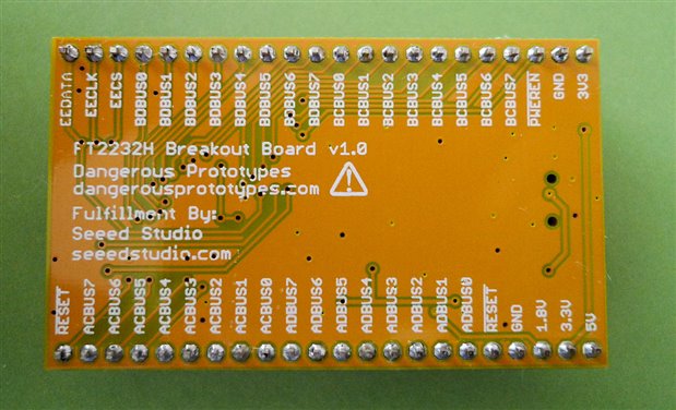
Note the 0403:6010 - this is the vendor and product ID respectively, in hex (needed later). The board doesn't come with any connector, so SIL headers need to be soldered. The reverse of the board shows the pin naming, and the circuit diagram is here.

image

The bitbang mode is brought out to the ADBUS[7..0] and BDBUS[7..0] pins. For input testing, I just pulled various pins high and low (i.e. to 3.3V and 0V) through a 1k resistor (in case a pin was accidentally still an output) and for output testing a multimeter was used (an LED and resistor would be fine too).

Software introduction

Generally, hi speed I/O may require kernel drivers; in the case of the FT2232H this is no different, but it is already part of Linux images. Some code and libraries are required as part of the application. This is explained in the diagram below.

image

The application software will be the area of interest, where the data is received and transmitted and any processing with the end data is handled. To connect to the kernel driver, a couple of libraries of code need to be linked in to the application code; these are libftdi (open source library for many FTDI ICs) and libusbx which provides a consistent API regardless of if the OS is Linux or Windows.

Building the software

This was quite simple; three downloads are required:

libftdi (download here) - I used version 1-1.0

libconfuse (download here) - version 2.7 - this is used for parsing text files for configuration purposes

libusbx (download link) - version 1.0.16

Create a folder off your home directory (e.g. called 'development') and create a folder called usb inside it.

The three downloads were extracted in the usb folder.

Installing libconfuse 2.7:

./configure
make
make install

(installs in /usr/local/include,lib and share)


For libusbx 1.0.16:

./configure --disable-udev
make
make install

(installs in /usr/local/libusb-1.0 and /usr/local/lib)


For libftdi 1-1.0, the makefiles are intended to be built with cmake, which I didn't have installed (and is a little unfamiliar to me) - however it is possible to build the code from the command line easily, there are not a lot of commands.

In the folder where libftdi was extracted, traverse to the 'src' folder. Then copy ftdi_versio_i.h.in to ftdi_versio_i.h and replace the variables marked with '@' with a custom value. In other words, modify the following lines so that this is how they appear, and then save the file.

#define FTDI_MAJOR_VERSION 1
#define FTDI_MINOR_VERSION 1
#define FTDI_MICRO_VERSION 0

const char FTDI_VERSION_STRING[] = "1-1.0";
const char FTDI_SNAPSHOT_VERSION[] = "0";

In the same src folder, compile like this:

gcc -c ftdi.c -I/usr/local/include/libusb-1.0
gcc -c ftdi_stream.c -I/usr/local/include/libusb-1.0
ar rs libftdi.a ftdi.o ftdi_stream.o
cp libftdi.a /usr/local/lib/.
cp ftdi.h /usr/local/include/.

Now the code in ftdi_eeprom can be compiled (path is development/usb/libftdi1-1.0/ftdi_eeprom). It requires a file ftdi_eeprom_version.h to be created in a similar manner as before.

#define EEPROM_MAJOR_VERSION 1
#define EEPROM_MINOR_VERSION 1
#define EEPROM_VERSION_STRING "1-1.0"

Type these commands to compile it:

gcc main.c -I/usr/local/include/libusb-1.0  -I/usr/local/include -I. -L/usr/local/lib -lftdi -lusb-1.0 -lconfuse -o ftdi_eeprom
cp ftdi_eeprom /usr/bin

Then example code files can be compiled as shown here for instance (path is development/usb/libftdi1-1.0/examples):

gcc simple.c -I/usr/local/include/libusb-1.0  -I/usr/local/include -L/usr/local/lib -lftdi -lusb-1.0 -o ftdi_simple
cp ftdi_simple /usr/bin

There is an another example program in the same folder, called bitbang_ft2232.c but it needs a small change; replace where it says 0x6001 (product ID) with 0x6010 in two places, and then compile:

gcc bitbang_ft2232.c -I/usr/local/include/libusb-1.0  -I/usr/local/include -L/usr/local/lib -lftdi -lusb-1.0 -o bitbang

When the bitbang program is run, it will just slowly toggle some pins (bits 0 and 1) on the two ports.

As an experiment, the code was modified to toggle pins with no delay for thousands of times; a speed of about 20,000 writes per second is possible, allowing for 10kHz square-waves (this was not measured on a scope, so it is just a guideline). Bitbanging in this manner will not have real-time accuracy like the PRU. (The FIFO mode that the FT2232H is capable of will be far better than bitbanging too, but needs to still be tested. However, bitbanging is still suitable for some purposes). Note: See comments section below. Accuracy is extremely poor with the bitbang way; an alternative method using buffers is available on the FTDI and that method should be investigated.

A quick program was created to test inputs in bitbanging mode too, and it reads input values at a similar speed. The program is attached (very untidy for now - it's late in the evening! but it works). The program reads the AD[7..0] pins repeatedly, and displays the 8-bit value in hex on the screen. Run it, and it will display lots of 0xff on the screen (the inputs appear to float high) and pulling low (1k resistor to 0V) on any of the input pins will make the text change.

To compile the code:

gcc bbtest.c -I/usr/local/include/libusb-1.0  -I/usr/local/include -L/usr/local/lib -lftdi -lusb-1.0 -o bbtest


Summary / Next Steps

To a large extent the PRU capability has rendered this almost redundant, but it's good to know that it is easy to interface high-speed data in several ways with the BBB now. The FTDI device is easy to use because a ready-built board is available, but equally it is easy to include the IC on a PCB where a USB interface is not currently available. Experimenting with the FIFO modes will be interesting.


Part 2: FIFO mode

A "synchronous FIFO" mode is available on the FT2232H, which is supposed to allow far higher rate I/O. In order to enable this, an EEPROM needs to be programmed. There is a ftdi_eeprom program that was compiled earlier (see above), however it did not work. The alternative is to just download a Windows executable called FT_PROG and use that.

Download FT_PROG from here  (PDF help file is here).

Run FT_PROG, click on the magnifying glass icon ("scan and parse") to read the board EEPROM. It will display as lots of FFFF, since it is a blank part.

image

On the left side device tree, expand to FT EEPROM->Hardware Specific->Port A->Hardware, and change the property from RS232 UART to 245 FIFO, which is needed for the FIFO modes to function. Repeat for Port B.

Then, go to File->Save as Template (e.g. my245fifotemplate.xml).

Select the Device:0 on the device tree, right click, and select 'Program device'. It should be virtually instantaneous, and the Device Output will show some new values instead of FFFF.

You could confirm all is well by restarting the FT_PROG application and clicking the scan icon again, and viewing the EEPROM contents.


Once this is done, unplug the FT2232H from the Windows maching and plug it back into the BBB. There is code in the examples folder called stream_test.c, and it is compiled in a similar manner as the other examples:

gcc stream_test.c -I/usr/local/include/libusb-1.0  -I/usr/local/include -L/usr/local/lib -lftdi -lusb-1.0 -o ftdi_stream_test
cp ftdi_stream_test /usr/bin

The program can be run by typing:

ftdi_stream_test -n dump.bin

It will capture data at a very high speed and dump to a file (unformatted raw bytes), whenever the *WR pin (pin 27 on the FT2232H-R chip, or P3_17 (ACBUS3) on the ready-built board is pulled low.

The '-n' suppresses error messages when bytes are skipped.

It appears that bytes are guaranteed to skip, and I'm guessing this is because there is a delay writing to the filesystem. With a very short *WR pulse (of the order of tens of nsec) the number of bytes written to file appear to be close to the expected value (assuming that the FT2232H is trying to capture at 60MHz). At any longer pulse, bytes are skipped. For further investigation!

Attachments:
bbtest.c.txt.zip
  • Sign in to reply

Top Comments

  • Former Member
    Former Member over 12 years ago +3
    A couple of observations as I'm just delving into libftdi for a second time... Lots of the libftdi code has hard coded device id's that dont cover all of the available ftdi devices. For example the ftdi_usb_find_…
  • Former Member
    Former Member over 12 years ago +2
    I forgot to say, your diagram shows libftdi & libusbx sitting on top of a driver. That's slightly misleading. While there will be a driver of some sort for the USB host port that will be there regardless…
  • Former Member
    Former Member over 12 years ago in reply to shabaz +2
    shabaz wrote: The white box being the Linux standard USB driver or Windows, etc. That's sort of my point.. plug a FTDI chip into a windows machine and you get the D2XX and/or Standard COM port drivers…
  • riverliu_sz
    riverliu_sz over 8 years ago in reply to shabaz

    I suffer from the same issue. I am using i.mx6ul with a cortex-A7 core running at about 500MHz. And for ftdi device, it is FT232H with d2xx driver. I connect FPGA and arm via FT232H, and FPGA sends 8192x16bit data to PC every 700us(=187Mbps).  Received data is only checked for error during running.


    In above test condition, PC always gets data error after about 6 times FT_read with 64KByte.


    I tried some test cases by reducing throughput, after I reduced it to 512x16bits per 700us, that is only 11.7Mbps, the data error disappered.


    The probelm happens on both gcc-4.6-softfloat and gcc-4.9-hardfloat.


    I must mention the same code compiled with x86 lib runs error-free on intel i5 plus Windows with throughput > 200Mbps.

    • Cancel
    • Vote Up 0 Vote Down
    • Sign in to reply
    • More
    • Cancel
  • shabaz
    shabaz over 12 years ago in reply to Former Member

    Hi Selsinork,


    As an experiment I disabled the writing to the filesystem (i.e. run "ftdi_stream_test -n" with no filename) , and just kept a count of bytes received; it's disappointing, but it seems some other buffer is overflowing, because it  skips a large proportion of bytes; I believe a buffer somewhere is extremely low - maybe just a few hundred bytes, which means at 60MHz sampling it is guaranteed to overrun almost instantly. I'm probably receiving 1Mbyte per sec if I don't write to disk (not bad, but nowhere close to 60Mbyte!).


    As you say, writing to a filesystem incurs an overhead - with writing enabled, I see about 100kbyte per sec (these are very much simple approximations - I've not accurately timed!).


    I agree with your conclusion that high-speed data with the FT2232H does require some additional circuitry and storage buffer but the OBLS does all this anyway already. Oh well, it was worth an experiment!


    More interestingly perhaps, when I wanted to test controlling the *WR line for very short periods, I didn't use a pulse generator (and my very old analog function generator is exhibiting some odd behavior currently) - it was easier to just use a quick PRU program to pulse a line in increments of 5nsec! So it makes a nice simple pulse generator.. (In fact it was possible to assemble the code on the fly, by just calling system("pasm...") in the C code of course; someone should modify the pasm source to use it like a library rather than just as an executable.


    P.s. Thanks for all the information today - it certainly helped accelerate getting to understand these FTDI devices in more detail.

    • Cancel
    • Vote Up 0 Vote Down
    • Sign in to reply
    • More
    • Cancel
  • Former Member
    Former Member over 12 years ago

    It appears that bytes are guaranteed to skip, and I'm guessing this is because there is a delay writing to the filesystem. With a very short *WR pulse (of the order of tens on nsec) the number of bytes written to file appear to be close to the expected value (assuming that the FT2232H is trying to capture at 60MHz). At any longer pulse, bytes are skipped. For further investigation!

    That's likely to be a USB limitation, remember USB 2.0 is 480Mbit/s so at it's theoretical maximum, divide by 8 and you get 60MB/s. Effective throughput is much less due to protocol overheads and any other devices on the bus. Think about a keyboard that's operating at 1.5Mbit/s on the same bus, how much of your theoretical 60MB/s gets lost when a single bit takes 320 times as long to send ?


    Also, when you're doing this on a BBB think in terms of the overall system, can you write to the eMMC or SD card at 60MB/s, or even 30MB/s, probably not. If you're using a USB hard drive then you fall foul of only having a single USB port and having to share the bandwidth.  Network perhaps ?  No as it's only a 100Mbit/s network port.  So you're left with writing to buffer cache which will get flushed to storage later, but if we assume 60MB/s and only 512MB RAM at least some of which is already in use you won't get long before you've exhausted that resource as well.


    So the 60MHz advertised rate only works so long as you can empty, or fill the usb buffers in the 2232 fast enough, after that you either have to pause to catch up or start dropping captured samples on the floor.


    For me this detracts quite a lot from using USB connected stuff for anything serious as you basically need to put a microcontroller, fpga or similar onto the other end of the usb cable to do the interesting stuff for you. It needs enough local memory to meet whatever the requirement is since it can't guarantee it can pass it back over usb quickly enough.


    There's things like the Open Bench Logic Sniffer that do exactly this, and scaled up a bit you could look at the BBB connected to your bigger PC over usb in much the same way image

    • Cancel
    • Vote Up +2 Vote Down
    • Sign in to reply
    • More
    • Cancel
  • Former Member
    Former Member over 12 years ago in reply to shabaz

    For reference, the reason I originally got interested in the ftdi stuff was this project

    http://www.huitsing.nl/irftdi/


    While I know others had more success, I could never get it to work reliably and that's why I started investigating whether the device could actually clock data in/out at a particular rate as the datasheet suggested. Turns out that it's never quite so simple and the comments on the sample accuracy and setting the baud rate to power-of-2 show that quite clearly.


    Interestingly, while looking for that article, I found this page selling these commercially http://www.irblaster.info/usb_receiver.html

    Given that my experience was that the ones connected to a real RS232 port worked fine (don't need any of this RT nonesense image ), but the ftdi versions were mostly useless for that application I'm intrigued that someone has done that.


    Interesting comment in the linked blog post http://www.irblaster.info/blog/2010/02/alberts-ftdi-ir-receivertransmitter.html is that the chip they used samples at 32x rather than 16x.  I don't see any mention of the exact chip they used, but it looks a lot like the FT232RL I used in their photos.

    • Cancel
    • Vote Up 0 Vote Down
    • Sign in to reply
    • More
    • Cancel
  • Former Member
    Former Member over 12 years ago in reply to shabaz

    shabaz wrote:


    and how the baud rate setting  can be used to control the input/output rate! I suppose they repurpose the UART clock present in the silicon for bitbang mode!


    Yes, there's some application notes on the FTDI web site that explain the details, but basically you're supposed to be able to do something like this, where RXBUFSZ is something large, say 8192 so that you're not paying a penalty for every change being a discreet usb transaction


    ftdi_set_baudrate(&ftdic, baud_rate);

    unsigned char buf[RXBUFSZ];

    int i;

    for(i=0;i<RXBUFSZ;i++) {

          buf[i]=(i & 1);

    }

    while (1) {

         do {

              ret=ftdi_write_data(&ftdic,buf,sizeof buf);

         } while (ret>0);

    }


    and the data is clocked out at 16x the baud rate which with that snippet in theory gives a square wave, but put a scope on it and see what you get... With a FT232RL it wasn't.


    See AN232R-01 from http://www.ftdichip.com/Support/Documents/AppNotes.htm for the details.

    • Cancel
    • Vote Up +2 Vote Down
    • Sign in to reply
    • More
    • Cancel
<>
element14 Community

element14 is the first online community specifically for engineers. Connect with your peers and get expert answers to your questions.

  • Members
  • Learn
  • Technologies
  • Challenges & Projects
  • Products
  • Store
  • About Us
  • Feedback & Support
  • FAQs
  • Terms of Use
  • Privacy Policy
  • Legal and Copyright Notices
  • Sitemap
  • Cookies

An Avnet Company © 2026 Premier Farnell Limited. All Rights Reserved.

Premier Farnell Ltd, registered in England and Wales (no 00876412), registered office: Farnell House, Forge Lane, Leeds LS12 2NE.

ICP 备案号 10220084.

Follow element14

  • X
  • Facebook
  • linkedin
  • YouTube