


Part 2: Introduction
This project is about connecting a screen from a laptop to the RIoTboardRIoTboard. For a full introduction, see part 1 by clicking here, it goes into more detail about this project. This part 2 covers the circuit and powering up the display.
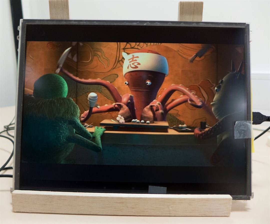
Here is an example photo of the result (wood mock-up stand, it will be tidied up later), this is a 12.1 inch display from a laptop. The RIoTboard is temporarily attached to the rear of the display:

How does it work?
The RIoTboard has a low-voltage differential signalling (LVDS) connector that sends data at very high speed (hundreds of MHz) in a serial form to an LCD display panel. The LCD display panel is responsible for deserializing the data back into a parallel format that the LCD display driver can understand. The advantage of this is that very few wires are required to transmit video from the RIoTboard to the LCD panel.
So, all that needs to be done is to connect up wires from the LVDS connector up to the LCD panel of choice. The LCD panel will require a certain voltage supply to operate. The backlight - often an LED backlight or a cold-cathode fluorescent lamp (CCFL) - will also require power. The particular LCD panel I used had a CCFL backlight and these require quite a high voltage (hundreds of volts) so an off-the-shelf inverter was used to generate this voltage. LED backlights require a far lower voltage.
The photo below shows the entire project, with everything taped to the back of the LCD panel to temporarily test everything out. The RIoTboard can be seen on the left (red board). Bottom-right is the main board I created which generates the required voltages to drive the LCD panel and the backlight.

Here is an annotated photo. It will be described in detail next:

Circuit Overview
There’s not much to the circuit except power supplies (on the board marked ‘Main Board’ in the photo above. The RIoTboard LVDS interface directly connects to the LCD display. The Main Board contains two main power supplies; one to drive the panel, and another for the backlight. The two voltages will vary depending on the panel chosen.
In order to have some flexibility, adjustable DC-DC converters were used so that they can be set to the desired voltages to suit different LCD panels. The DC-DC converters were off-the-shelf Texas Instruments (TI) modules, PTH04000WAH PTH04000WAH (step-down converter to drive the LCD panel) and PTN04050CAH PTN04050CAH (step-up to drive the backlight).
The LCD panel I used required 3.3V to function, and a 12-24V supply to drive the inverter to create the high voltage (HV) supply (>600V) for the cold cathode fluorescent lamp (CCFL). No inverter is needed for LED backlight panels.
The circuit for the two power supplies is shown below. The DC-DC converter U1 is used to generate a 3.3V supply to drive the LCD panel. U4 is used to step-up from 5V input up to 15V to drive the CCFL inverter which generates >600V. Different voltages can be set as can be seen in the table in the circuit diagram below (it depends on what input voltage the inverter requires), and the diagram shows the voltage set to 6V. In order to set to 15V, R12 should be 68 ohms, and R13 is not fitted.
The circuit has lots of ‘do not fit’ resistor locations that can be experimented with if it is desired to run the entire circuit and the RIoTboard from a single supply source.

The printed circuit board (PCB) that was created is shown below (the files are attached below so you can order your own from any PCB manufacturer). The board was designed to be cut into several pieces. The main board contains the two DC-DC converter modules and all associated circuitry. There is space for a variable resistor in case one is needed for dimming some displays.

The right side of the board is used to create some ‘breakout boards’. This is because it can be tricky making connections to the small connector on the LCD panel, and the mini LVDS connector on the RIoTboard. Therefore these small breakout boards are used to help with the connectivity.
There is also a small breakout board for a ‘digitizer’. This is because the LCD panel I selected has a Wacom digitizer covering the screen, for pen input. I wanted to attempt to use that with the RIoTboard too (I have not attempted it yet).
Selecting and Using a TFT LCD Panel
In theory many LCD panels should work. It was decided to select a slightly older panel with a reasonable resolution of 1024x768. Higher resolutions may require extremely high speed LVDS signalling and the wiring could get very critical.
It is worth selecting a nice panel such as an In-Plane Switching (IPS) one, which will allow great viewing angles. The panel I used was HT12X21-351 from e-bay. This panel can be found in IBM X41 tablet notebooks, therefore has good viewing angles. The X41 tablet version panel came with a built-in pen digitizer, Wacom model SU-040-X01. There is a non-tablet version and the digitizer is absent.
This is what the LCD connector looks like on the back of the LCD panel. Different model LCD panels may have a different connector:
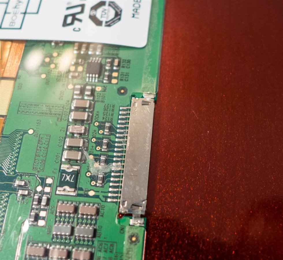
The connector has 1mm pitch pins, however it is extremely hard to crimp a mating connector without the correct tool. Therefore the metal shell was removed (gently ripped off with an old pair of wire cutters):
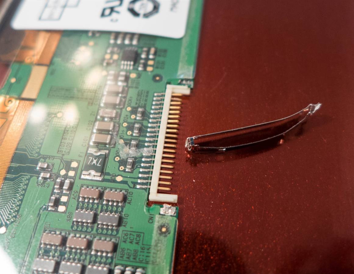
Then, the breakout board was directly soldered onto the pins:
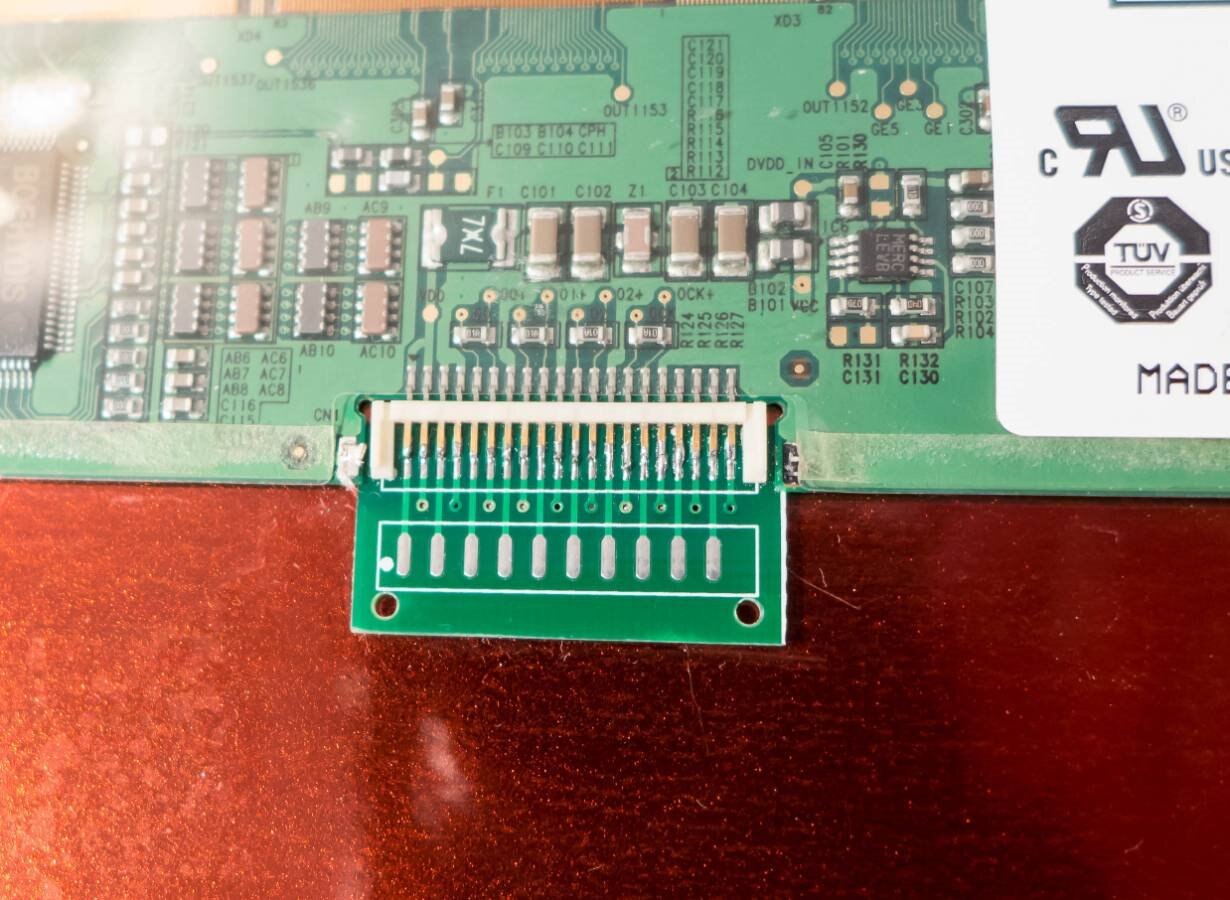
This is eventually where I needed to get to:

More on that later, but it is probably easier to solder these wires on first (the wires are discussed next), and then solder the breakout board onto the LCD panel connector to end up with the result seen in the photograph above.
Selecting Cables
LVDS signalling is carried over pairs of wires. The communication from the RIoTboard to the LCD panel is carried over four pairs of wires. The cable is fairly critical. One option is to try Ethernet cable however in the end I decided to use the internals of a SATA cableSATA cable. The photo below shows the insides of the cable with the plastic insulator stripped off. The cable has two pairs of wires. The outer screen and braid was removed, leaving just the twisted pairs with inner screen intact.
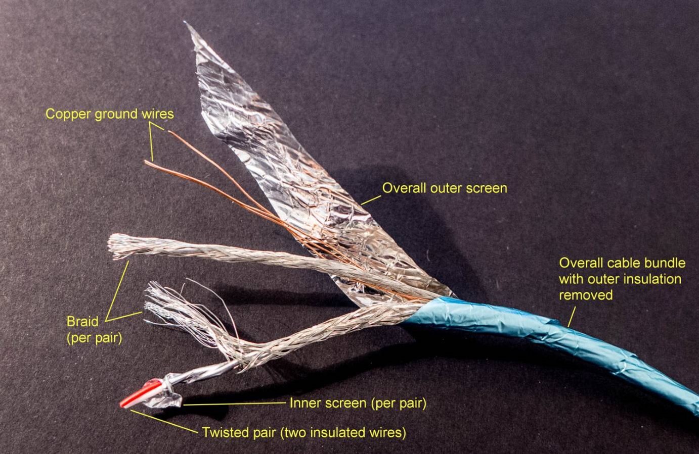
Some recommendations when creating the LVDS signalling connections are:
- Keep the cable lengths all exactly identical
- Untwist the bare minimum at each end, and keep the remainder twisted (don’t over-twist the remainder either; keep it exactly as it was)
- No sharp bends; try to make them curved
Once the connections were made, the copper ground wire was twisted around all the pairs to keep the screens all at the same voltage, and to keep a tidy bundle.
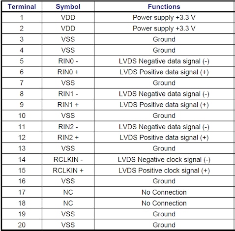
The LCD panel I used had the following pinout:
RIoTboard LVDS Interface
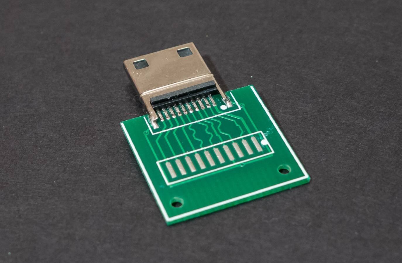
The RIoTboard uses a mini HDMI socket for LVDS signalling. A breakout board was created and soldered to a mini HDMI plugmini HDMI plug as shown here. This requires the printed circuit board thickness to be 0.8mm instead of the more usual 1.6mm.
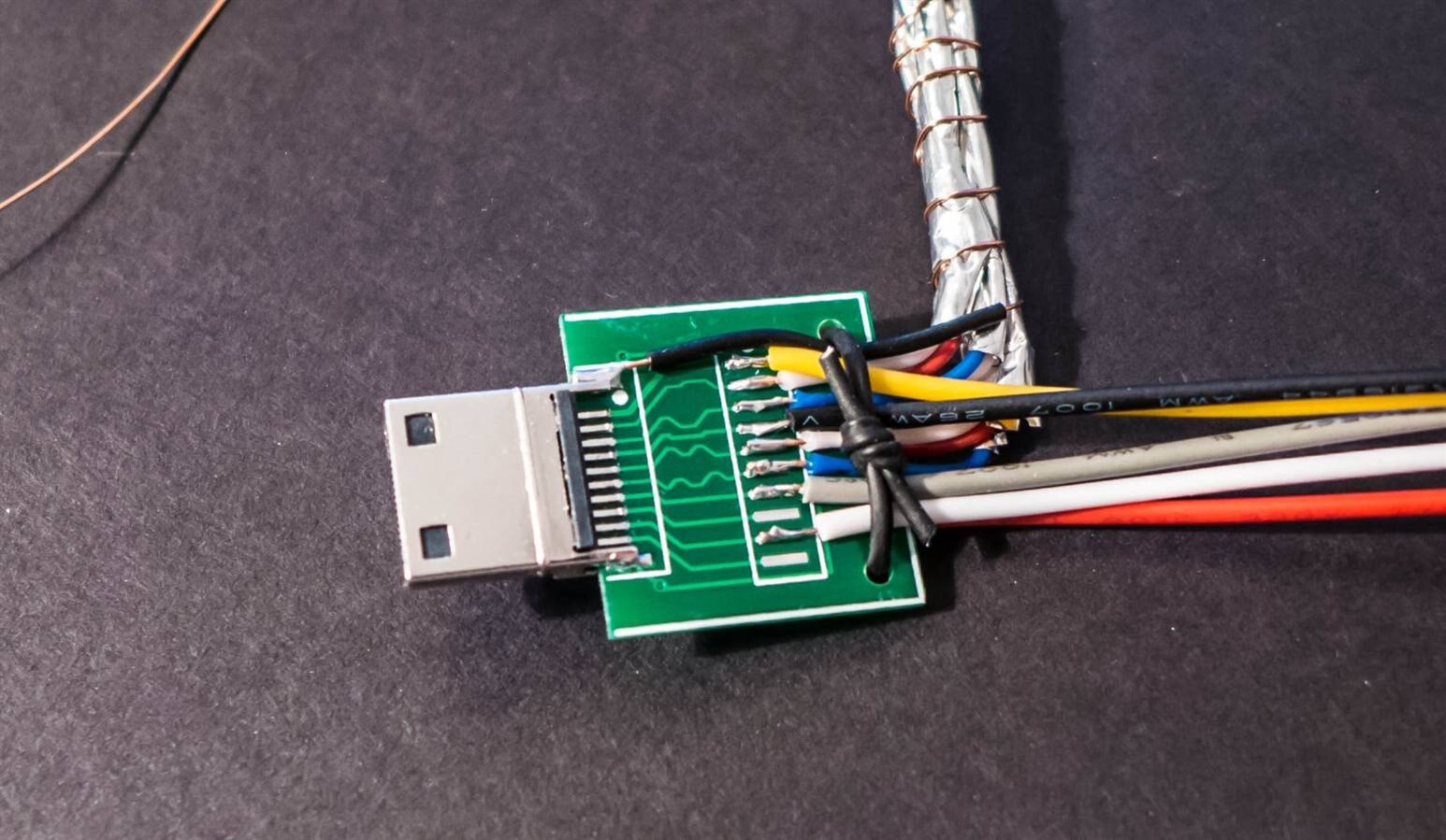
The differential signalling wire pairs were soldered on to end up with the result shown below.
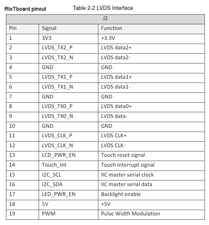
Information on the pinout is available by viewing the RIoTboard schematic, or viewing table 2-2 in the RIoTboard user manual. The table is reproduced here:
Constructing the Main Board
The main board contains the two DC-DC converters mentioned earlier. The photo below shows what it looks like, assembled and taped onto the LCD panel. There is not a lot to the main board.

Cold Cathode Fluorescent Lamp (CCFL) Inverter
The particular LCD panel that I used had a CCFL backlight instead of an LED backlight. This meant that I needed an inverter to get from 15V to >600V. I purchased a cheap inverter (less than £3) from ebay (search for “5-28V 5mm Ultra-thin High Voltage Universal LCD Inverter for Laptop”). Here it is taped onto the LCD panel:

RIoTboard Configuration
The RIoTboard by default generates video on the larger full-size HDMI connector. This needs to be disabled, and LVDS signalling needs to be enabled on the mini HDMI connector.
To do this, a USB to 3.3V serial adapterUSB to 3.3V serial adapter is needed. The adapter is plugged into the serial port (three wires into J18 on the RIoTboard). The pinout is:
Green: pin 1 (marked with a triangle on the RIoTboard); transmit from RIoTboard point of view
Red: pin 2; receive from RIoTboard point of view
Black: pin 3; 0V
The USB end is plugged into a PC and the PC terminal software configured for 115200 baud and Flow Control is set to XON/XOFF.
Next, the RIoTboard is powered up. As soon as text begins to appear on the terminal, press space until the system halts at a bootloader prompt. Enter the following commands (for Android):
setenv bootargs console=ttymxc1,115200 init=/init nosmp video=mxcfb0:dev=ldb,bpp=32 video=mxcfb1:off fbmem=10M vmalloc=400M androidboot.console=ttymxc1 androidboot.hardware=freescale
saveenv
Now power off the RIoTboard. Everything is now ready to go!
Powering up
The 5V supply to the main board can now be connected up. Then, power up the RIoTboard. You should see an Android startup screen launch. Plug in a mouse, and you should be able to unlock the screen and begin using Android.
Summary
The information here will allow an LCD panel to be interfaced to the RIoTboard successfully. The next step is to create an enclosure to house it, so that the temporary wood stand can be finally discarded.
The main board also has space to connect up the digitizer portion of the LCD panel to the RIoTboard, so that pen capability can be enabled. That’s for another day too.
The full circuit diagram, parts list with order codes and plot (Gerber) files for the PCB are attached. The PCB files can be sent to any PCB manufacturer. Just specify that a 0.8mm thickness PCB is required.
If you try a different TFT LCD panel, do report back so that a list of tested panels can be recorded to help others.
 | |
 | |

