Hi everyone. I am attempting to use the RIoT Board as the basis for a HMI design. I hope to document my progress in this forum. My only other experience configuring and building an embedded Linux/Android device is with the Beaglebone Black so I will be learning about the I.MX 6 and RIoT Board along the way.
My plan is to make a "shield" or "cape" style adapter board which breaks out all of my required I/Os and allows me to connect a parallel RGB LCD and capacitive touch panel.
I plan on configuring the RIoT board with the following I/Os:
- Parallel RGB Display Port
- I will be attempting to use the LG LB043WV2-SD01 LCD.
- 4.3"
- 480 x 800 px
- 18 bit RGB
- Datasheet: http://www.hy-line.de/fileadmin/hy-line/computer/csv/datasheets/LB043WV2-SD01(Industrial)_FinalCAS_V1.0_120315.pdf
- I will be attempting to use the LG LB043WV2-SD01 LCD.
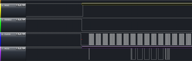
- 1 x SPI Port
- For initializing the LCD.
- 1 x I2C Port
- For communicating with the Capacitive Touch panel. (I have not nailed down a specific panel yet.)
- 1 x UART
- For communicating with external equipment. I will be including level translation on my adapter PCB.
- 2 x PWM
- One for controlling RGB LEDs and one for controlling a buzzer.
After examining the RIoT board User Manual, the I.MX 6 datasheet and the Freescale I/O Mux Tool I believe my goal can be achieved with the following pin mux:
| Pin | Signal | Function | CPU Ball | LCD Signals | LCD Function (18 Bit RGB) | My Desired Usage |
|---|---|---|---|---|---|---|
| 1 | VDD_NVCC | 3.3V | ||||
| 2 | 5VIN | 5V | ||||
| 3 | GND | GND | ||||
| 4 | GND | GND | ||||
| 5 | GPIO4_16 | GPIO | N19 | DI0_DISP_CLK | Pixel Clock | |
| 6 | CSPI3_CLK | SPI3 clock | P24 | DISP0_DAT0 | B0 | |
| 7 | GPIO4_17 | GPIO | N21 | DI0_PIN15 | Data Enable | |
| 8 | CSPI3_MOSI | SPI3 master output salve input | P22 | DISP0_DAT1 | B1 | |
| 9 | GPIO4_18 | GPIO | N25 | DI0_PIN2 | Hsync | |
| 10 | CSPI3_MISO | SPI3 master input salve output | P23 | DISP0_DAT2 | B2 | |
| 11 | GPIO4_19 | GPIO | N20 | DI0_PIN3 | Vsync | |
| 12 | CSPI3_CS0 | SPI3 chip select 0 | P21 | DISP0_DAT3 | B3 | |
| 13 | CSPI3_CS1 | SPI3 chip select 1 | P20 | DISP0_DAT4 | B4 | |
| 14 | CSPI2_CS1 | SPI2 chip select 1 | T22 | DISP0_DAT15 | R3 | |
| 15 | GPIO4_31 | GPIO | R21 | DISP0_DAT10 | G4 | |
| 16 | CSPI2_MOSI | SPI2 master output salve input | T21 | DISP0_DAT16 | R4 | |
| 17 | GPIO5_05 | GPIO | T23 | DISP0_DAT11 | G5 | |
| 18 | CSPI2_MISO | SPI2 master input salve output | U24 | DISP0_DAT17 | R5 | |
| 19 | GPIO5_06 | GPIO | T24 | DISP0_DAT12 | R0 | |
| 20 | CSPI2_CS0 | SPI2 chip select 0 | V25 | DISP0_DAT18 | *NC | |
| 21 | GPIO5_07 | GPIO | R20 | DISP0_DAT13 | R1 | |
| 22 | CSPI2_CLK | SPI2 clock | U23 | DISP0_DAT19 | *NC | |
| 23 | GPIO5_08 | GPIO | U25 | DISP0_DAT14 | R2 | |
| 24 | UART3_RXD | UART3 receive data | G22 | UART3_RXD | UART3_RXD | |
| 25 | GPIO4_26 | GPIO | R25 | DISP0_DAT5 | B5 | |
| 26 | UART3_TXD | UART3 transmit data | F22 | UART3_TXD | UART3_TXD | |
| 27 | GPIO4_27 | GPIO | R23 | DISP0_DAT6 | G0 | |
| 28 | UART4_RXD | UART4 receive data | V6 | ALT0, ecspi1.ECSPI1_MOSI | ||
| 29 | CSPI3_RDY | SPI3 data validation | R24 | DISP0_DAT7 | G1 | |
| 30 | UART4_TXD | UART4 transmit data | W5 | ALT0, ecspi1.ECSPI1_SCLK | ||
| 31 | I2C3_SCL | I2C3 master serial clock | R4 | I2C3_SCL | ||
| 32 | UART5_RXD | UART5 receive data | U6 | Unused | ||
| 33 | I2C3_SDA | I2C3 master serial data | T3 | I2C3_SDA | ||
| 34 | UART5_TXD | UART5 transmit data | U7 | ALT0, ecspi1.ECSPI1_MISO | ||
| 35 | I2C4_SCL | I2C4 master serial clock | R3 | Unused | ||
| 36 | PWM1 | Pulse Width Modulation | R22 | DISP0_DAT8 | G2 | |
| 37 | I2C4_SDA | I2C4 master serial data | R5 | Unused | ||
| 38 | PWM2 | Pulse Width Modulation | T25 | DISP0_DAT9 | G3 | |
| 39 | GND | GND | ||||
| 40 | PWM3 | Pulse Width Modulation | C20 | PWM3 |
It looks like I'm already short one PWM. Rats. Maybe I'll need to switch to an I2C controlled LED or use the Audio Out for the buzzer.
My first step will be to rebuild the standard RIoT board Android image from source. (The source is still downloading. : ) ) Although I may chmod 777 the UARTS in the init.rc file so I can experiment with the Android Serial Port API (https://code.google.com/p/android-serialport-api/wiki/Building_the_project) sample program.
Then I will try to rebuild the image with one of my desired pin muxes. Maybe SPI 1. That being said I'm not sure how to change the pin mux. I guess I'll be editing the board-mx6solo_RIoTboard.c file in some way.