Let me start by saying that i'm new to using simulation tools, so it's probably a rookie mistake, but.
In my design i have a LM385(DR) (dual) opamp and want to simulate the circuit.
I 'created' the schematic symbol, i downloaded the spice model from the Texas instruments website, i added it to the symbol (like in this video).
I ran in to problems,
1) The LM385 is a dual opamp so i made the symbol with two opamp parts and 1 power supply part
I have not been able to get the power pins connected, keep getting error that the part has to few pins.... i can't get past this error and can't save the symbol with simulation data.
2) Created a new symbol with 2 opamp parts with the power pins in the same symbol (like in the video)
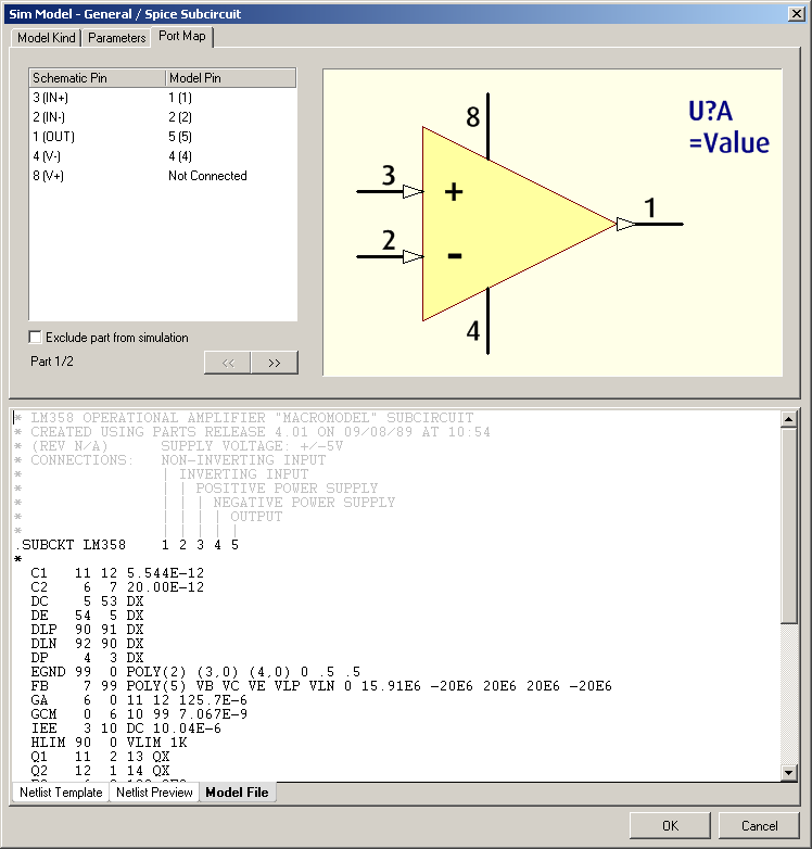
That seemed to go a lot better, i entered the link to the simulation data, edited the pin mapping data and was able to save the symbol + sim data.
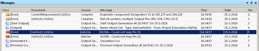
However when trying to run the simulation i got an error that (simulation) pin 3 (that is V+) was not connected, strange, i know i entered it.
Back to the sim edit, it showed that power pin 8 (= spice model pin 3) was not connected, so i changed it to pin 8, checked the other opamp and saved it.
Just for fun i re-opened the editor and checked it again, what do you know... pin 8 (should be model pin 3) was again not connected....
What am i doing wrong here (in symbol variant 1 and 2) ????