
Summary:
During my search for a low cost electronics learning module, I came accross the ADALM1K which has interesting features for the price point (approx. 70$). It incorporates a source measure unit (SMU), an oscilloscope and a function generator. On top of that the hardware and software is open-source which is a learning experience in itself to undestand how the kit works.
My goal was first to test how the kit works overall. Once I had some confidence in its usage functions, I dived deeper into its evaluation / application software to look for automation oppurtinites with Python, where one could automate custom workflows for measurement and learning purposes.
I was able to integrate the ADALM1K with my Raspberry Pi setup and automate its functionality using the provided libsmu/pysmu Python package from Analog. I ended up creating a small Python library (pytest-analog) around libsmu so I could write some automated tested for my projects usning the ADALM1K.
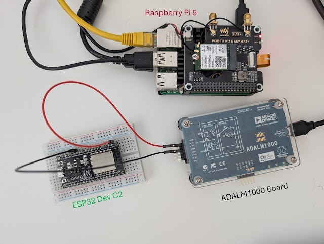
As an example, I created automated test cases via Python to measure the power consumption of a DUT (ESP32 Dev board). This could be extended to create more complex test cases for your system under test using very low cost equipment such as the ADALM1K
Hardware:
The main hardware sepcs are as follows:
- Two channels supporting measure and source function simultaneously: voltage (0 to 5V) or current output (- 200 to +200mA)
- Two fixed power supplies (2.5V and 5V) supprting up to 200 mA current draw
- 16-bit (0.05%) basic measure accuracy with 4 digit resolution
- Four digital signals (GPIOs 3.3V CMOS)
 |
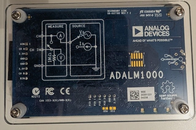
| ADALM1K Block diagram per SMU Channel (wiki.analog.com) |
As per the above the diagram, an analog channel on the ADALM1K combines a function generator and an oscilliscope instrument on the same pin. In Rev F of the board, the analog ouput and input functions could be seperated with the two provided addiotnal split pins such that the oscillscope function is brought out along with 1 MΩ from the function generator function. Therefore, each analog channel could be configured to one of the following options:
- Source Voltage and Measure Current (with / wihtout Split IOs)
- Source Current and Measure Voltage (with / wihtout Split IOs)
- High Impedance (with / wihtout Split IOs)
If you would like to learn more about the ADALM1K hardware and its design, the following resources are good to read through:
 |
| ADALM1000 Board Upside View |
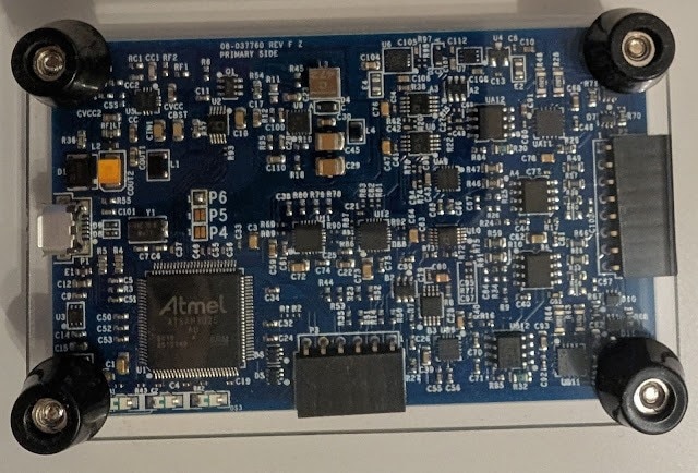 |
| ADALM1000 Board Underside View |
Software:
The software landscape of the ADALM1K comprises the device firmware and the host software which can run on different platforms (Winodws / Linx / OS-X).
The ADALM1K firmware runs on an Atmel based microcontroller. The host software includes a C++ library (libsmu) containing the abstractions for streaming data to and from ADALM1K via USB. In addition, the Pixelpulse 2 and ALICE GUI-based tools are available to control the ADALM1K and make measurements with it.
Testing with Analog Discovery:
In order to test the opertion of the ADALM1K via the provided GUI software Pixelpulse 2 and ALICE, I did some basic checks to test the ADALM1K analog and digital inputs/outptus via my Analog Discovery 3 (another great electronics learning tool). In these tests, I connected the two instruments to my PC and started their host softwares simultaneously to feed inputs and read outputs.
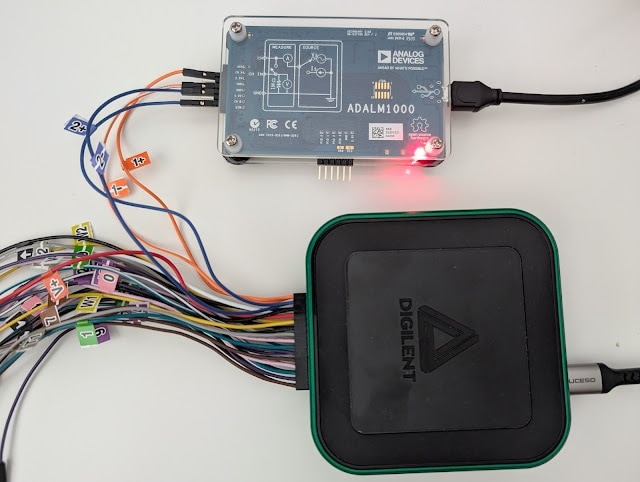
Test 1: Checking analog outputs of the ADALM1K via the Analog Discovery scope channels:
As shown in the image below, I connected the ADALM1K source channels A, B to the Analog Discovery scope channels 1, 2. Then using ALICE software I configured an output voltage on channels A, B and then read measured voltages on the scope channels via the WaveForms software of Analog Discovery 3. I configured channels A, B to output 3.6, 1.2 V. On the Analog Discovery, I read approximately similar values on channels 1, 2. There is a slight 200 mV deviations which also seem to occur when I set the ADALM1K to ouput 0 V. Therfore, the ADALM1K requires some calibration before doing any real testing.

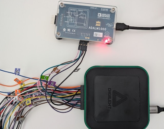
Test 2: Checking GPIOs state of the ADALM1K via the Analog Discovery digital channels:
In this test, I connected the ADALM1K GPIO pins (0-3) to the Analog Discovery Digital IOs (0-3). Using ALICE software, I have set the ADALM1K GPIOs to a defined high / low state and then checked if the same state is read on the Analog Discovery side using its Static IO instrument in the WaveForms software. I was able to confirm the GPIOs state (high for pins 0,1 and low for pins 2,3
)

Integration with Raspberry Pi:


Python Wrapper and Test Automation:
After integrating the ADALM1K with my Raspberry Pi setup and getting familiar with the libsmu / pysmu libraries, I decided to create a small python library (wrapper class) to ease the control of the instrument functions and also create pytest-fixtures for setting up / tear down of the instrument in an automated testing environment. The library is named pytest-analog and it also support the automation of the Analog Discovery instrument from Digilent.
To demonstrate the usage of ADALM1K with pytest-analog in automated testing context, I created a small python test case where the ADALM1K would measure the power consumption of an ESP32 microcontroller running different sketches.
Given the instrument source and measure capabilites, it can power the ESP32 with a given voltage and measure drawn current simultaneously.
The steps to create an automated test with the ADALM1K via pytest-analog are listed below:
- Create an empty workspace folder (e.g pytest_analog_tmp) and navigate to it (In bash terminal):
- mkdir pytest_analog_tmp && cd pytest_analog_tmp
- Create a Python virtual environment to install pytest_analog and its dependencies in isolation:
- python3 -m venv venv
- . venv/bin/activate
- python3 -m pip install --extra-index-url https://test.pypi.org/simple/ pytest-analog
- python3 -m pip install matplotlib
- Create an empty "pytest.ini" file to provide the ADALM1K configuration at the start of the test with the content below.
[pytest]
# pytest options
addopts = -v --capture=tee-sys

# Filtering Warnings
filterwarnings =
    ignore::DeprecationWarning

# Logging Options
log_cli=true
log_level=INFO
log_format = %(asctime)s %(levelname)s %(message)s
log_date_format = %Y-%m-%d %H:%M:%S

# ADALM1000 Fixtures Options
# Voltage Source
adalm1k_ch_a_voltage = 3.30
adalm1k_ch_b_voltage = 0.00 - Create a test_esp32_current_consumption.py file with the content below:
import numpy as np
import pytest
import time
import math
import logging
import matplotlib.pyplot as plt
from pytest_analog import ADALM1KWrapper, AnalogChannel
from datetime import datetime

def test_esp32_current_consumption(
    adalm1k_voltage_source: ADALM1KWrapper
) -> None:

    # 2000 samples collected at base rate 100 kHz with averaging every 1000 samples -> 20 seconds
    MEASUREMENTS_COUNT = int(2000)
    # Do some averaging over collected data
    AVERAGE_RATE = int(1e3) # average every 1 / AVERAGE_RATE, Default sampling rate of ADALM1K is 100 kHz

    samples = []
    ch_a_avg_voltage = []
    ch_a_avg_current = []

    # Read incoming samples in a blocking fashion (timeout = -1)
    for _ in range(MEASUREMENTS_COUNT):
        samples.append(adalm1k_voltage_source.read_all(AVERAGE_RATE, -1))

    # Average captured readings
    for idx in range(MEASUREMENTS_COUNT):
        # voltages in V
        ch_a_voltage = [sample[0][0] for sample in samples[idx]]
        # currents in mA
        ch_a_current = [sample[0][1] * 1000 for sample in samples[idx]]

        ch_a_avg_voltage.append(np.mean(ch_a_voltage))
        ch_a_avg_current.append(np.mean(ch_a_current))

    logging.info(f"Average current consumption: channel A: {np.mean(ch_a_avg_current):.3f} mA")
    logging.info(f"Max current consumption: channel A: {np.max(ch_a_avg_current):.3f} mA")

    # plot current profile
    t = np.arange(0, MEASUREMENTS_COUNT) / (100e3 / AVERAGE_RATE) # Default sampling rate is 100 kHz
    fig, ax = plt.subplots()
    fig.suptitle(f"ESP32 Blinky current consumption", wrap=True)
    fig.supxlabel("Time (s)")

    ax.plot(t, ch_a_avg_current, color='red')
    ax.set(ylabel= "CH_A I(mA)")
    ax.margins()
    ax.set_xlim([0, math.ceil(np.max(t))])
    ax.grid(True, which='both')
    ax.minorticks_on()

plt.savefig(f"I_consumption_esp32_blinky_{time.strftime(datetime.now().strftime('%H%M'))}.png")- Run the test using pytest: pytest test_esp32_current_consumption.py which generates the following logs in the terminal.

 |
| Current consumption profile for ESP32 blinking an LED every 2 seconds |
 |
| Current consumption profile for ESP32 going into deep sleep mode for 5 seconds then waking up shortly |
After the test execution, a graph is generated with the measured current consumption profile during the test. The graphs above are for two different sketches running on the ESP32.
The first one is a basic blinky sketch where one could certainly see an increase in current draw when the LED is on. The duration of those peaks match closely with the LED-On period as expected.
The second sketch showcases the ESP32 deep sleep mode for extreme power saving applications, where the device is consuming a couple of miliamps during sleep mode and then waking up shortly every 5 seconds.
IMPORTANT: The above results can be inaccurate and require verification with a professional equipment to compare how good the ADALM1K is in capturing power characterstics of a given DUT.
Top Comments