


We addressed the requirements and circuits needed within a variable speed drive (VSD) to provide the main control power supply and the power supplies for the inverter electronics – namely gate drivers and current sense circuits in the previous blog in the series.
These are highlighted once again in graphical form in Figure 1, which shows a generalized view of a typical VSD architecture.
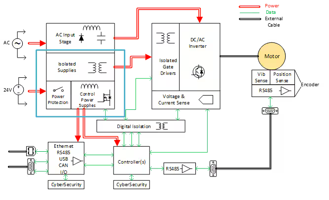
Figure 1: Detailed Variable Speed Drive Architecture
This blog addresses two more important power supply topics within the highlighted block of the VSD in Figure 1:
- protecting the main control power supply
- deriving the downstream low-voltage point-of-load (POL) power rails (these were referenced in the last blog, but not specifically addressed).
Control Power Protection
Protection of the main control power supply (usually 24V) from transients and anomaly conditions is extremely important within a VSD. The reason for this is that there are generally two paths for this supply rail. The first path is that described in the last blog in which the 24V control power supply is derived from the AC mains, or high voltage DC bus via an isolated power conversion stage. However, this 24V rail can also usually be supplied directly from an auxiliary power input connected to the VSD. Most automation environments distribute 24V supplies around the control cabinets for a range of control equipment, and the VSD usually taps into this supply. This auxiliary 24V input is usually diode OR’ed with the converter-derived 24V supply, to ensure that only one supply source is active at a time. The advantage of having this available is that even if the AC mains drops out or trips, usually the auxiliary 24V supply will keep running, meaning the VSD’s control electronics can stay energized, resulting in the capability to quickly restart the VSD and not lose any context information. The disadvantage is that the VSD power supplies are now exposed to all of the voltage transients existing on the factory-wide 24V supply system – these can occur through switching loads that excite voltage ringing on distribution cables, lightning events that propagate through the system, electrostatic discharge from nearby electric fields or human contact, as well as electromagnetic interference picked up on cables. Hence the a need for solid protection on this auxiliary supply input.
The VSD functional safety standard IEC 61800-5-2 Annex A (Section B.3.2) shows a recommended Power Supply (PS) and Voltage Monitor (VM) subsystem for such a 24VDC rail. It consists of protection against a variety of common faults such as reverse polarity, overcurrent, and voltage transients.
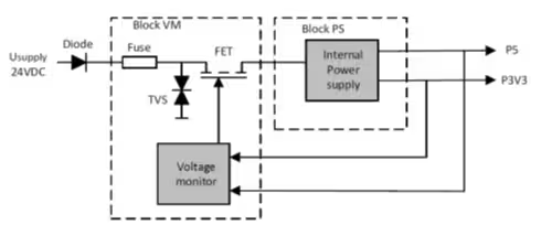
Figure 2: Recommended auxiliary supply protection per IEC 61800-5-2
As the transients involved can vary in energy level and duration, designing a discrete circuit can be time-consuming and prone to error, and may have poor long-term reliability. Integrated solutions such as Analog Devices Surge Stopper family integrate all of the IEC 61800 requirements, including input reverse polarity detection and protection, overcurrent, short circuit and inrush current detection and protection, and high voltage transient disconnect.
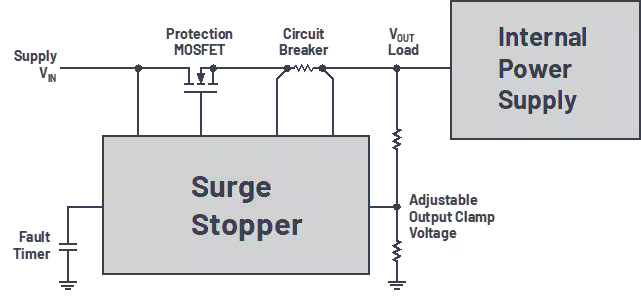
Figure 3: Analog Devices’ Surge Stopper implementation of IEC 61800-5-2
Figure 3 depicts the use of surge stopper solutions from Analog Devices as a potential implementation of IEC61800-5-2 protection recommendations. Components such as the LT4363 or the integrated MOSFET variant LTC4381 can provide robust and reliable protection solutions for the main control power supply.
Low Voltage Point-Of-Load (POL) Power
Downstream of the main control power supply sit the low voltage (<12V) power rails. These are by and large the point-of-load (POL) supplies that directly power the main controller devices (CPU, FPGA), other digital components (memory, transceivers, interfaces) analog circuitry (ADC, DAC, op-amps, etc), and I/O devices and terminals. The specific design of these power architectures is unique to each VSD, and it is difficult to speak in generalizations, but the typical approaches to these power supplies are illustrated in Figure 4 and Figure 5. In Figure 4, single-stage switching regulators are utilized for some key low voltage rails, with downstream low-dropout (LDO) regulator being added for noise-sensitive analog rails or very low current rails at lower voltage levels.
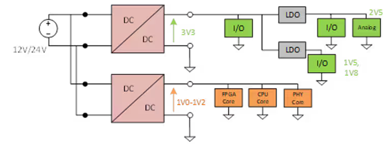
Figure 4: Single-stage switcher approach
In Figure 5, a single intermediate rail is generated (in this case 5V) and this is further stepped down to individual rails as needed by the POL devices. Also shown here, is the potential need for startup sequencing or tracking of supply rails, which can be important in the complex multi-controller systems used in many VSDs.
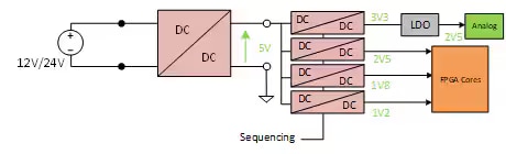
Figure 5: Multi-stage switcher approach
POL power supply architecture design is complex and involves many tradeoffs related to overall efficiency, cost, space, and noise. Tools such as LTpowerCAD, LTpowerPlanner, and LTSPICE, from Analog Devices can significantly ease the design challenge.
Summary
This blog has completed the topic of power supplies within the VSD, underlining the importance of protection circuits for the main control power supply, and touching on the challenges related to POL low voltage supply design. In the next blog post, we will start looking at the main DC/AC inverter stage that implements the power conversion to control the motor itself.


