


We examined the power inverter, the power electronics block that sits at the heart of every motor drive, in the previous blog in this series . It is the controllable power element that enables modulation of the power to the motor in order that its speed and torque can be precisely controlled. Control of the inverter is thus critical to the whole operation of the drive. For any closed loop control system we generally need a set point (e.g. the desired operating point) and a measured variable (known as feedback) to compare it with, in order that the control loop can respond to any difference between these. In drives, the key measured variables are typically motor current, and motor position. Other variables such as DC bus voltage are helpful to the operation of the control loop. In this blog, we will examine the current feedback and the DC bus voltage measurement as these occur within the inverter stage described in the last blog, as indicated again in our architecture diagram below.
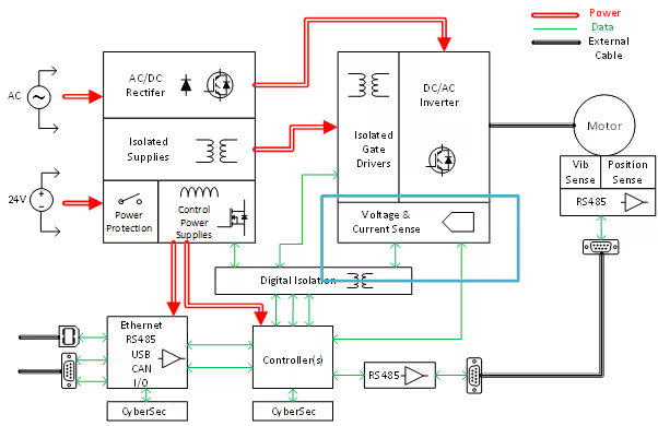
Figure 1: Servo Drive Architecture Diagram
What is important in the current feedback path is that the measurement is synchronized with the PWM cycle in order that no high frequency switching current ripple is introduced into the feedback path. This requires precise timing of the current sampling in order that it is sampled at the midpoint of the waveform. At this point in the waveform, the instantaneous current is equal to the PWM cycle average, and the measurement will not include any of the PWM switching ripple current. This is illustrated in Figure 2 in a simplified fashion – where the sampling point on the phase current waveform is shown, along with its relative alignment to the PWM high-side switching waveform, and the switching period Tsw. The PWM_SYNC pulse indicates the point at which sampling of the current must be triggered in this scenario (this can also be understood as the center-point of the digital filter in the case where sigma-delta ADC type sampling is used which is not a single-point sample, see [1])
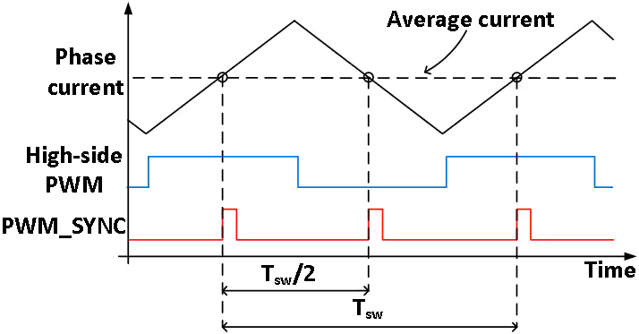
Figure 2: Motor current mid-point sampling
Simultaneous sampling of at least two phases is also required, and usually 14-16 bit measurement resolution is sufficient, with microsecond-level latency so that the control loop can respond within the PWM cycle time (Tsw) or in half the cycle time for higher performance control loops.
There are a few different ways to implement the current measurement – these are shown in Figure 3, and described in the table below, along with some example part numbers to implement the scheme for a 20A application. The most accurate location to measure the motor current is in the actual motor phases, i.e the output lines of the inverter – but this usually requires galvanic isolation, due to the high voltage present at these nodes. Motor current measurements can be inferred from other locations such as inverter leg, and DC bus positive or negative rail – however these measurement locations, while potentially cheaper to implement have other disadvantages associated with them.
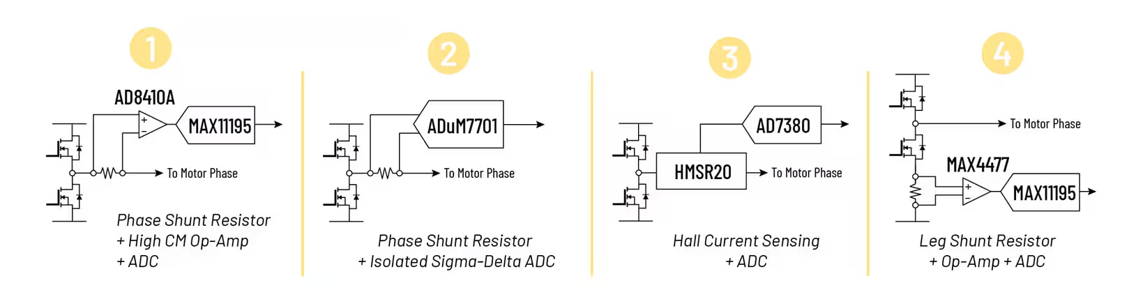
Figure 3: Current feedback options
|
|
Description |
Comments |
Example Parts (20A) |
|
1 |
Series shunt resistor + high common mode voltage (CMV) op-amp + simultaneous sampling ADC (SSADC) |
Usually used in <100V applications, as high CMV op-amps are usually rated for this range. |
CFN1206AFXR010 (Bourns) AD8410 (ADI) MAX11195(ADI) |
|
2 |
Series shunt resistor + isolated ADC |
Best solution for noise immunity, size and performance. Bitstream output – needs digital filter |
CFN1206AFXR010 (Bourns) ADuM7701-8 |
|
3 |
Isolated current sensor + opamp + SSADC |
Good solution for higher current levels where shunt resistors become too inefficient |
HMSR 20-SMS (LEM) AD8515 (ADI) AD7380 (ADI) |
|
4 |
Leg shunt resistor + opamp + SSADC |
Cheapest solution as no isolation needed if controller is DC bus grounded. Less accurate than in-phase shunt |
CFN1206AFXR010 (Bourns) MAX4477(ADI) MAX11195(ADI) |
High fidelity, precision, current feedback is important to the overall control loop of the inverter. It has a big impact on the overall control bandwidth and torque ripple. Bandwidth translates into faster transient performance of the motor control – which can be very important in applications like pick-and-place machines. Torque ripple translates into effects such as machining quality and finish tolerance in applications like grinding, cutting and polishing.
While current feedback is the most important feedback variable from the inverter to the controller, DC bus voltage can also be valuable as a control feedforward variable. It is not used as a controlled quantity, but because variation in the DC bus voltage impacts the dynamics of the current control loop it can be used as a feedforward variable, which improves the dynamics of the overall current controller. The end result of this is as shown in Figure 4.
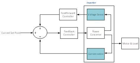
Figure 4: Current Controller Block Diagram
The DC bus voltage sense signal can be derived directly from a voltage divider across the DC bus if the controller ground is at the DC bus negative, or else by using an isolated amplifier or ADC (such as the ADuM7701 mentioned previously) connected to the voltage divider output.
The next blog will look at another important feedback variable – position sensing – that is utilized in another part of the motor control system in conjunction with the current and voltage sensing described in this blog post.
References
[1] “Part 1: Optimized Sigma-Delta Modulated Current Measurement for Motor Control” by Jens Sorensen, Dara O’Sullivan, and Shane O’Meara, https://www.analog.com/en/resources/analog-dialogue/articles/optimized-sigma-delta-modulated-current-measurement-for-motor-control.html