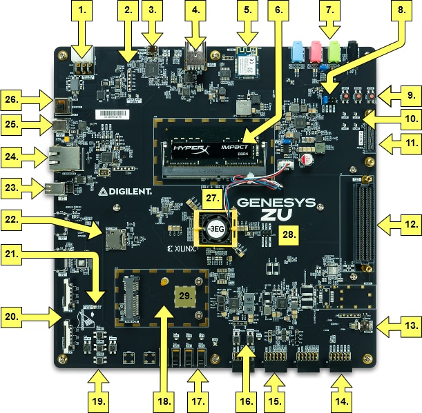
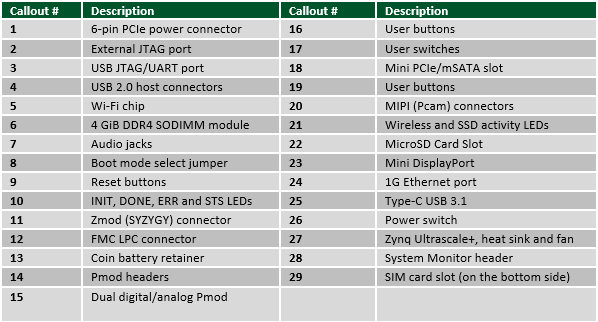
Digilent Genesys ZU-3EG is an advanced computing platform loaded with Xilinx Zynq Ultrascale+ MPSoC EG and a range of peripherals and interface. Let's take a closer look.
Memory
Main memory is a single-slot populated DDR4 SODIMM, always upgradeable by the user. It is wired to the Processing System (PS) side using the hard-core memory controller. The bundled module is a 4GiB Kingston HyperX HX424S14IB/4. There is also a serial flash memory from ISSI. This memory is used to provide non-volatile code and data storage. It can be used to initialize the PS subsystem as well as configure the Programmable Logic (PL). The flash memory is also commonly used to store non-configuration data needed by the application. If doing this from a bare-metal application, the flash memory can be freely accessed using standalone libraries included with a Xilinx SDK BSP project. If doing this from a Petalinux generated embedded Linux system, the flash can be partitioned as desired and mounted like a standard Memory Technology Device (MTD) block device. The microSD connector has a hinge-based mechanism. It is compatible with UHS-I allowing 1.8V signaling and speeds up to SDR104, or 104MB/s.
Platform MCU
Tying all the features of the Genesys ZU together into a computing platform requires an embedded controller which is called Platform MCU. Part of the platform is the coin battery, the fan, a temperature sensor inside the Zynq Ultrascale+ MPSoC EG device and Power Management Units (PMU). Management is done through dedicated signals or over the main I2C bus. The Platform MCU is implemented by a Microchip ATmega328PB. It is on the auxiliary 3.3V power domain, immediately available after power-up. This power domain is independent of the PMUs which provide main power, giving the Platform MCU control over main power. It also shares the main I2C bus with the Zynq Ultrascale+ MPSoC EG device, giving it access to all the critical peripherals. Other features include Zynq Ultrascale+ MPSoC EG device temperature sensing, fan speed control, and VADJ voltage setting. The Platform MCU program memory has two sections:
- Application where the firmware resides
- Bootloader where the bootloader resides.
Software Support
Digilent provides an out-of-the-box Petalinux project and Vivado Webpack project. There are free IP-support for the following peripherals
- DDR4 memory controller
- MIPI CSI-2
- DisplayPort controller
- Ethernet 1G
- USB 2.0/3.0
- PCIe Root/Mini PCIe
- SATA/mSATA
- On-board Wi-Fi/SPI controller
Network Interface
- 1G Ethernet
The Genesys ZU uses a TI DP83867CR PHY to implement a 10/100/1000 Ethernet port for wired connectivity. After power-up, the PHY starts with Auto Negotiation enabled, advertising 10/100/1000 link speeds and full duplex. If there is an Ethernet-capable partner connected, the PHY automatically establishes a link with it, even with the Zynq Ultrascale+ MPSoC device is not configured.
- Wi-Fi
Microchip ATWINC1500 module provides 2.4GHz IEEE 802.11 b/g/n wireless network connectivity. It interfaces to the PS-side of Zynq Ultrascale+ MPSoC EG device over SPI, supporting a maximum theoretical data rate of 48Mbps. The module can be used in bare-metal applications with the full IP stack included in the firmware loaded from flash. It is also supported in Linux in the ATWILC1000-compatible mode, where the firmware is loaded on-the-fly upon boot and the OS IP stack is used.
- WLAN, Bluetooth, WWAN
The Mini PCIe socket allows users to connect any wireless radio module compatible with the PCIe Mini Card standard. With both PCIe x1 and USB 2.0 available in the socket, the dual Wi-Fi/Bluetooth modules can be used. User can use the SIM slot to bring in WWAN radio on board.
USB Interface
- USB Full-Featured Type-C
USB 3.1 Gen1 and USB 2.0 support is handled by the Full-Featured Type-C receptacle. The connector has a USB 2.0 pair for backward compatibility, one high-speed transceiver lane (two pairs) for USB 3.1, and configuration channel (CC). Since the plug is reversible, the upper and lower rows double the number of pins for each function, designated by suffixes 1 and 2. Plug orientation is established during the configuration process over the CC1 and CC2 pins. Depending on the orientation, either pins with suffix 1 or pins with suffix 2 carry actual signals. Multiplexing 1 and 2 for the USB 3.1 lane is done by an on-board hardware multiplexer.
- USB 2.0 Host
Host-only USB 2.0 functionality is implemented by a Microchip USB3320 PHY and a Microchip USB2513B hub. The PHY is wired to the PS-side controller of Zynq Ultrascale+ MPSoC EG device over ULPI. The hub has three Downstream-Facing Ports. Two of these connect to a dual-stacked Type-A connector, providing 0.5A current per port. The third port is connected to the MiniPCIe slot, an embedded USB port.
- USB 2.0 - JTAG/Serial Bridge
The micro Type-B connector connects to an FTDI FT4232HQ USB bridge. It provides a JTAG interface for programming and debugging, one UART interface connected to the Zynq Ultrascale+ MPSoC EG device and one UART interface connected to the Platform MCU. The UART interfaces are exposed as standard COM ports.
Multimedia
- DisplayPort
The dual-lane mini DisplayPort connector is wired to a PS-side DisplayPort Controller of Zynq Ultrascale+ MPSoC EG device via two PS-GTR transceiver lanes. Resolutions up to 4Kx2K@30fps are supported at a maximum 5.4Gbps line rate.
- Audio Codec
The Genesys ZU-3EG includes an Analog Devices ADAU1761 SigmaDSP audio codec complementing its multimedia features. Four 1/8” (3.5mm) audio jacks are available for line-out, headphone-out, line-in, and microphone-in. Line-out, headphone-out and line-in jacks are stereo and the microphone input is mono. To record or play back audio, the audio data needs to be converted. The audio codec bridges the gap between the analog jacks and the digital FPGA pins. It connects to the PL side of the Zynq Ultrasacle+ MPSoC EG device. Analog-to-digital and digital-to-analog conversion is done at up to 24 bits and 96 kHz sampling rate. Digital audio data is carried to/from the FPGA on a serial, full-duplex interface, which supports several different formats, the default being I2S. This interface is clocked by the FPGA through BCLK by default, but the codec can be configured to provide the clock itself. Configuring the audio codec can be done over I2C. The codec is clocked from the FPGA through the Master Clock (MCLK) pin. A clock must be provided for the codec to function, including the I2C port. The exact frequency depends on the desired sample rate and whether PLL will be used, but 12 MHz is a good start.
- MIPI ports
The two MIPI ports are 15-pin, 1 mm pitch, zero insertion force (ZIF) connectors designed specifically for attaching Digilent PCAM 5C, 5MP camera sensor modules, to Genesys ZU-3EG. It allows for bi-directional D-PHY lanes thanks to direct I/O support in the UltraScale+ architecture. Therefore, it also supports MIPI DSI applications.
Mini PCIe / mSATA
It is compatible with PCI Express Mini card types F1/F2 (Full-Mini) and H1/H2 (Half-Mini) and mSATA card types Mini and Full size. Mechanical compatibility is assured by the relocatable stand-offs included in Genesys ZU-3EG. Electrically, the SATA lane and the PCIe x1 lane share the same PS-GTR transceiver lane. Therefore, it is up to the MPSoC configuration to enable either the SATA or the PCIe Root controller and map it to the GTR lane. Mini PCIe modules can also make use of the embedded USB 2.0 port wired to the on-board USB hub and the MPSoC USB1 controller up the chain.
Expansion Port
- Low-Pin Count FMC Connector
The Genesys ZU includes an FPGA Mezzanine Card (FMC) Standard-conforming carrier card connector that enables connecting mezzanine modules compliant with the same standard. All user defined signals are bonded to the PL-side of the Zynq Ultrascale+ MPSoC EG device.
- Zmod
The Zmod port uses the SYZYGY Standard interface to communicate with installed SYZYGY pods. Each SYZYGY Standard interface contains 14 single-ended I/O pins (2 of which I2C), 8 differential I/O pairs (which can alternatively be used as 16 additional single-ended I/O pins), and two dedicated differential clocks - one for input and one for output. The Zmod port is wired to PL-side Zynq Ultrascale+ MPSoC EG device powered by the VADJ rail, sharing them with FMC signals.
- Pmod
Pmod ports are 2×6, right-angle, 100-mil spaced female connectors that mate with standard 2×6 pin headers. Each 12-pin Pmod port provides two 3.3V VCC signals (pins 6 and 12), two Ground signals (pins 5 and 11), and eight logic signals
Oscillators
The PS on Genesys ZU-3EG has a clock source of 30MHz while the PL has a clock source of (by default) 25MHz
Coin battery
A Seiko TS621E lithium rechargeable battery provides power to the Zynq Ultrascale+ MPSoC EG device Battery Power Domain (BPD) through the VCC_PSBATT pin. It is connected in parallel with a 100 uF capacitor. The BPD includes the real-time clock with a dedicated crystal oscillator and a RAM available for storing a secure configuration key. The capacitor alone can provide power for approx. 15 minutes after main power is turned off. The battery will provide power after that.
You can have the detailed information from Genesys ZU-3EG reference manual


