


Introduction
Working with a data acquisition system (DAQ) often feels straightforward—especially when you’re only measuring one channel. But once you expand beyond that and bring multiple inputs into the mix, things can get tricky. You might connect a sensor, verify its output with a multimeter like the Fluke 77, and everything seems fine. But when you try the same with your DAQ, the results suddenly don’t line up. At that point, it’s easy to assume something’s wrong with the device. But in reality, many issues stem from how DAQs handle multiple channels, and how those channels interact behind the scenes.
This article breaks down some of the most common DAQ-related issues and explains what you can do to make your measurements more reliable.
Get to Know Your DAQ First
Before diving into troubleshooting, it’s worth asking a fundamental question: what kind of DAQ are you using? Specifically, does it have simultaneous inputs—where each channel has its own dedicated analog-to-digital converter (ADC)—or is it a multiplexed device that uses a single ADC to cycle through multiple inputs?
The distinction matters. Simultaneous-input DAQs, like the USB-1808X or USB-1608FS-Plus, tend to be easier to work with and more accurate in multi-channel setups. These types often use one ADC per channel, either in a single integrated chip or across multiple chips, as in the case of devices like the MCC 172 or WebDAQ 504.
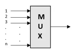
On the other hand, multiplexed DAQs—such as the USB-2416—use solid-state analog switches (MUX chips) to direct each channel sequentially to a single ADC. This approach reduces cost but introduces potential signal integrity issues due to shared circuitry and capacitance between channels.
What Happens Inside a Multiplexed DAQ
When a DAQ cycles between inputs using multiplexing, the small internal capacitance between channels can become problematic. Each time the system switches from one signal to another, it can create a kind of ghost image of the previous signal on the next channel. This is especially noticeable if one channel is connected and its neighbor isn’t—suddenly the inactive channel picks up a residual voltage.
One way to avoid this is by making sure that all channels—especially the unused ones—are either grounded or connected to a low-impedance source (ideally under 100 ohms). This helps dissipate any leftover charge quickly and allows the new channel to settle on the correct value. High-impedance circuits like resistor dividers can complicate things, especially on multiplexed systems, and should be used with caution.
Interestingly, resistor dividers can still work well on DAQs with simultaneous inputs. But on multiplexed systems, their effectiveness depends on timing. For example, some devices offer a “Burst Mode” that scans inputs rapidly with minimal delay between channels. That short delay may not be enough time for the residual charge to dissipate, leading to inaccurate readings.
If you're using resistor dividers with a multiplexed DAQ, it helps to disable burst mode and space out the sampling rate. Doing so gives the system more time between readings and reduces interference between channels. Just be aware that some devices, like the USB-1616HS, are always in burst mode, while others, like the USB-1608G, let you turn it off when needed.
Understanding Isolation
Isolation is another critical concept in DAQ accuracy. At its simplest, isolation means that there’s no direct electrical connection to earth ground. Devices that are isolated don’t share a ground path with the host computer, which helps eliminate ground loops and interference.
There are a few types of isolation. Device-level isolation separates the DAQ from the computer’s ground. If external power is used, internal transformers provide additional protection. Some DAQs go even further, offering channel-to-channel and channel-to-ground isolation, which is particularly useful when multiple signal sources or sensors might interact electrically.
A good multimeter like the Fluke 77 is battery powered, making it inherently isolated. That’s one of the reasons it’s so reliable for validating sensor readings—even in electrically noisy environments.
Ground Loops: The Hidden Culprit
One of the most common causes of strange DAQ behavior is a ground loop. This occurs when multiple paths to ground exist, which can introduce unwanted voltage into the measurement system. Even a small amount of extra voltage can skew sensor readings—especially when dealing with low-voltage signals like those from thermocouples.
Thermocouples are particularly vulnerable. Grounded thermocouples, for instance, can form a loop if their sensing junction is mounted on a conductive surface. Inside the DAQ, the system automatically ties the thermocouple’s low side to the analog reference when the input is set to thermocouple mode, increasing the chance for interaction between adjacent channels.
If you suspect a ground loop involving a thermocouple and another powered sensor, you have a few options. One is to isolate the thermocouple tip using insulating materials like Kapton tape (up to 500 °F), mica washers, or other non-conductive barriers. In more complex setups where multiple grounds are unavoidable, using channel-isolated modules can solve the problem. These modules not only condition the signal but also provide galvanic isolation between each channel and the system. Brands like Dataforth offer affordable models in the 8B series, though each can add around $100–$200 per channel to your system cost.
When Noise Gets In the Way
Electrical noise is everywhere—from power grids to motors, heaters, and industrial equipment. Many DAQ systems use sigma-delta ADCs, which are tuned to suppress 50/60 Hz noise from AC mains. But once frequencies shift—say from a motor ramping up or an oven heating—the digital filters can fall short.
Sometimes the fix is as simple as relocating your DAQ system further from the source of interference. USB cables with ferrite chokes can also help dampen high-frequency noise. And once again, isolation modules prove useful, as they often include low-pass hardware filters that block unwanted frequencies more effectively than software-based solutions.
A Simple Confidence Check
If you're unsure whether your DAQ is performing correctly, one of the easiest ways to verify is by measuring a known voltage source—like a battery. This might seem basic, but it’s an effective way to confirm that your hardware is functioning. A battery is stable, low-noise, and has low impedance—ideal for testing. If you're using a differential input, just connect a 100kΩ resistor between the low-side input and ADC ground to give the system a reference point.
Once you see that your DAQ measures the battery accurately, you can start reconnecting other signals one by one. This can help pinpoint where noise or error is creeping in. If things go wrong again, it’s often due to interference, improper grounding, or issues between channels.
Shielded wiring like coaxial cables or twisted-pair shielded wires can reduce some noise, but certain types of interference will still pass through—especially if the noise doesn’t fall within the filtering range of your ADC.
Final Thoughts
Multi-channel DAQ systems introduce a lot of moving parts, and small mistakes can quickly snowball into confusing results. Whether it’s unexpected readings due to multiplexing, signal bleed from high impedance, or elusive ground loops and noise, these systems require a deeper understanding of how inputs behave and interact.
The good news is that most of these issues have reliable solutions. Once you know what to look for—and how to isolate each component—you’ll be able to build more accurate, stable, and trustworthy measurement systems for your applications. Read the detailed blog post here.