element14 Community
element14 Community
    Register Log In
  • Site
  • Search
  • Log In Register
  • About Us
  • Community Hub
    Community Hub
    • What's New on element14
    • Feedback and Support
    • Benefits of Membership
    • Personal Blogs
    • Members Area
    • Achievement Levels
  • Learn
    Learn
    • Ask an Expert
    • eBooks
    • element14 presents
    • Learning Center
    • Tech Spotlight
    • STEM Academy
    • Webinars, Training and Events
    • Learning Groups
  • Technologies
    Technologies
    • 3D Printing
    • FPGA
    • Industrial Automation
    • Internet of Things
    • Power & Energy
    • Sensors
    • Technology Groups
  • Challenges & Projects
    Challenges & Projects
    • Design Challenges
    • element14 presents Projects
    • Project14
    • Arduino Projects
    • Raspberry Pi Projects
    • Project Groups
  • Products
    Products
    • Arduino
    • Avnet Boards Community
    • Dev Tools
    • Manufacturers
    • Multicomp Pro
    • Product Groups
    • Raspberry Pi
    • RoadTests & Reviews
  • Store
    Store
    • Visit Your Store
    • Choose another store...
      • Europe
      •  Austria (German)
      •  Belgium (Dutch, French)
      •  Bulgaria (Bulgarian)
      •  Czech Republic (Czech)
      •  Denmark (Danish)
      •  Estonia (Estonian)
      •  Finland (Finnish)
      •  France (French)
      •  Germany (German)
      •  Hungary (Hungarian)
      •  Ireland
      •  Israel
      •  Italy (Italian)
      •  Latvia (Latvian)
      •  
      •  Lithuania (Lithuanian)
      •  Netherlands (Dutch)
      •  Norway (Norwegian)
      •  Poland (Polish)
      •  Portugal (Portuguese)
      •  Romania (Romanian)
      •  Russia (Russian)
      •  Slovakia (Slovak)
      •  Slovenia (Slovenian)
      •  Spain (Spanish)
      •  Sweden (Swedish)
      •  Switzerland(German, French)
      •  Turkey (Turkish)
      •  United Kingdom
      • Asia Pacific
      •  Australia
      •  China
      •  Hong Kong
      •  India
      •  Korea (Korean)
      •  Malaysia
      •  New Zealand
      •  Philippines
      •  Singapore
      •  Taiwan
      •  Thailand (Thai)
      • Americas
      •  Brazil (Portuguese)
      •  Canada
      •  Mexico (Spanish)
      •  United States
      Can't find the country/region you're looking for? Visit our export site or find a local distributor.
  • Translate
  • Profile
  • Settings
Fluke
  • Products
  • Manufacturers
  • Fluke
  • More
  • Cancel
Fluke
Forum Problem with old Fluke Scopemeter
  • Blog
  • Forum
  • Documents
  • Events
  • Polls
  • Members
  • Mentions
  • Sub-Groups
  • Tags
  • More
  • Cancel
  • New
Join Fluke to participate - click to join for free!
Actions
  • Share
  • More
  • Cancel
Forum Thread Details
  • Replies 22 replies
  • Subscribers 25 subscribers
  • Views 9554 views
  • Users 0 members are here
  • fluke scopemeter
  • fluke 123
Related

Problem with old Fluke Scopemeter

mudz
mudz over 5 years ago

Today, I received my most awaited thing of this year... After a long long journey it finally reach me.. Hehe ..  enough with suspense talk..

Few months ago like 5 months.. I bid for a scopemeter on ebay. This was the first time I did bidding thing. Okay, what stupid thing I did now...  Alright, Bidding shot up to almost double and I ended up buying this Fluke 123 Scopemeter which has a line on the display image  image

Now after being stuck to customs for almost four months due to no invoice, I finally got the parcel and paid 40% custom duty. image

This thing cost me fortune I could have purchased a nice 2 channel oscilloscope. Stupid me.. (probably till now shabaz will be thinking, this guy is idiot I warned him many times before but he doesn't even listen).. image

Now, this meter is not turning on, I believe after 5 months of no activity battery is probably dead. So I thought to charge it first. There is always a but.. When I checked its adaptors output voltage it is 22.3 volts when it should be 15 volts.
imageimageimage


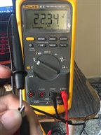
Anyone already has this scopemeter? Should I charge it with it? ebay sender told me it was working when he send me the item, but did not about voltages.


  • Sign in to reply
  • Cancel

Top Replies

  • Gough Lui
    Gough Lui over 5 years ago +6
    Is this a "heavy" wall-wart adapter? I suspect it might be a regular unregulated linear power supply. With old fashioned linear power supplies which are *unregulated*, the voltage will approximate the…
  • michaelkellett
    michaelkellett over 5 years ago +5
    You've got a modern flashy one ! Mine is a PM97 made by Philips (before Fluke bought the Scopemeter line from them). Don't know exactly how old but the calibration sticker is dated 2002 ! I haven't used…
  • michaelkellett
    michaelkellett over 5 years ago in reply to mudz +5
    Never used it much, and haven't for more than 15 years. It's just not good enough (50MHz, not much memory) for the kind of work I mainly do - so I often end carrying a bench scope about. Got it from where…
Parents
  • Gough Lui
    Gough Lui over 5 years ago

    Is this a "heavy" wall-wart adapter? I suspect it might be a regular unregulated linear power supply.


    With old fashioned linear power supplies which are *unregulated*, the voltage will approximate the peak of the rectified output voltage as they are designed to reach the output voltage only when the rated current is flowing. For a sine wave, the peak is 1.414 times the rated voltage -> 15 * 1.414 = 21.21V. What you measured is only slightly higher, which might reflect the mains voltage at your house being a little higher than 230V at the time of measurement.


    This behaviour seems normal for a heavy linear unregulated power brick. However, if you are extra concerned, try putting on a load and see if the voltage falls. For 15V/0.3A, that would correspond to a resistance of 50 ohms with a power rating of at least 4.5W for continuous load. So perhaps if you have a 5W wire wound resistance of about 47 or 56 ohms (common values), you could give it a try and it should be close to 15V if it's working right.


    - Gough

    • Cancel
    • Vote Up +6 Vote Down
    • Sign in to reply
    • Cancel
  • mudz
    mudz over 5 years ago in reply to Gough Lui

    Gough Lui  wrote:


    Is this a "heavy" wall-wart adapter? I suspect it might be a regular unregulated linear power supply.

    Yes this is, so damn heavy that I have to give it a thought of using it on wall plugs, as i was worried about plug pins might get broken due to the weight of rest of the body. image


    With old fashioned linear power supplies which are *unregulated*, the voltage will approximate the peak of the rectified output voltage as they are designed to reach the output voltage only when the rated current is flowing. For a sine wave, the peak is 1.414 times the rated voltage -> 15 * 1.414 = 21.21V. What you measured is only slightly higher, which might reflect the mains voltage at your house being a little higher than 230V at the time of measurement.

    I don't understand this concept, though I thought the same 15v*1.414v ~ 21v and considered that high voltage( ~252v at the time of measurement ) part too, but my question to myself was, this is Fluke we are talking about, if it's written 15V DC then it should be spot on 15v DC it should not behave like ac. what am I missing here? Robert Peter Oakes


    This behaviour seems normal for a heavy linear unregulated power brick. However, if you are extra concerned, try putting on a load and see if the voltage falls. For 15V/0.3A, that would correspond to a resistance of 50 ohms with a power rating of at least 4.5W for continuous load. So perhaps if you have a 5W wire wound resistance of about 47 or 56 ohms (common values), you could give it a try and it should be close to 15V if it's working right.


    - Gough

    At that time i thought about this as well, that it would drop its voltage after connecting to load because I was sure on two things that this adaptor was working fine as mentioned by sender and secondly it's fluke they sure have given a thought about this. Also, I was getting so much impatient with this meter, after almost waiting for 6 months to get this thing in my hands, I just didn't cared about it and plugged it in. image
    After few minutes I tried turning it on, but screen just flashes and turns of. I do hear two clicks every time I try to turn it on. Waiting for it to charge.

    • Cancel
    • Vote Up +3 Vote Down
    • Sign in to reply
    • Cancel
  • Gough Lui
    Gough Lui over 5 years ago in reply to mudz

    mudz  wrote:

    I don't understand this concept, though I thought the same 15v*1.414v ~ 21v and considered that high voltage( ~252v at the time of measurement ) part too, but my question to myself was, this is Fluke we are talking about, if it's written 15V DC then it should be spot on 15v DC it should not behave like ac. what am I missing here?

    It's 3:34am in Sydney, but seeing as I'm up, I thought I might as well take a shot at answering this -

    • First - imagine an AC transformer - 230V and 15V out. Ideal world = you put 230V AC one side and you get 15V AC out the other. This is the first "part" of the linear transformer.
    • But now you have AC and need DC, so you put that through a bridge rectifier - now you get a "bumpy" DC that swings from 0V to 15 x 1.414 = 21.21V depending on which part of the mains sine wave you're on.
    • Now you decide to smooth this out, so you chuck a capacitor on the output. No load + capacitor = holding the peak voltage throughout the cycle = 21.21V.


    If you still are unconvinced, you merely need to take a peek at a number of "Unregulated Power Supply Tutorials" to see how this works.


    As to why Fluke would have used it - consider the age of the equipment, the environment it is used in and the reliability needed. Fluke is known for bulletproof equipment - linear transformers are pretty much damn near bulletproof as they're simple and resistant to over-voltage and most amounts of vibration/shock of travelling about. The second thing has to do with the actual use - if it's used for charging Ni-Cd batteries, most of the time, the actual voltage is irrelevant as long as it's higher than the cells, as the "trickle" method just depends on the current being ~ C/10 (i.e. for 300mA charge current, you'd expect it to be charging a 3Ah pack at about 14-16h charge duration due to colombic efficiency). How this is done? Basically there's a resistor in series with the supply and the Ni-Cd cells. This was extremely popular in the old days of walkmans, MD players, cordless vacuums, rechargeable shavers, etc as a unintelligent method of charging which had low risk of failure. In fact, my Uniden scanner and Icom CB radio also use this exact method, and they're not exactly low cost equipment. Because of this arrangement, the cells reach a given voltage and the resistor dissipates the rest - there is no need for precision at all.


    Some will have more complex circuitry, of course, but that's placed in the device rather than in the wall wart because there is every chance that some desperate technician will try a cheapy Chinese "any voltage" replacement. This might be a timer-based cut-off or even a thermal-monitoring solution. Regardless of what it is, it will be expecting potentially "unsmooth" and "crude" voltage regulation if it was designed for use with an unregulated linear supply as any changes in the primary would be reflected into the secondary almost on perfect correspondence - i.e. 10% swing on mains = 10% swing in secondary output. Some of these are designed to handle a good amount of ripple - battery charging circuitry often won't care, while the actual electronics may rely on functioning rechargeable cells to act as an "infinite capacitor" to smooth out the input and regulate the voltage on which the remainder of the circuitry depends on.


    I'm sure some other pieces of equipment might probably still want to use this scheme for simplicity - if it were not for the fact that RoHS regulation basically makes Ni-Cd cells difficult to incorporate into products without a good reason, that Li-Ion has so much more volumetric and gravimetric energy density, and minimum energy performance/efficiency standards have pushed standby power so low that linear solutions cannot meet regulatory needs in this regard or efficiency under load. The transition to lighter switch-mode supplies has these benefits and is normally regulated by the virtue of a feedback circuit (either primary side sensing, feedback coil/optoisolator signal), but is not without its downsides though - e.g. RF interference, stress on capacitors leading to premature failure and increased complexity.


    - Gough

    • Cancel
    • Vote Up +4 Vote Down
    • Sign in to reply
    • Cancel
  • mudz
    mudz over 5 years ago in reply to Gough Lui


    It's 3:34am in Sydney, but seeing as I'm up, I thought I might as well take a shot at answering this

    I appreciate it image


    you put 230V AC one side and you get 15V AC out the other. This is the first "part" of the linear transformer.


    Actually its an dc adaptor, So i was expecting 15v DC output only irrespective of the RMS value of AC voltage fact. But due to the fact it's an unregulated power supply, that's how it behaves. Amazing.. Thank you
    T
    his https://www.sparkfun.com/tutorials/103  link was very informative.. learned new thing today.

    • Cancel
    • Vote Up +2 Vote Down
    • Sign in to reply
    • Cancel
  • Gough Lui
    Gough Lui over 5 years ago in reply to mudz

    You misunderstood - I was trying to explain the whole concept of an unregulated DC supply in stages.


    The first stage is an AC to AC transformer - 230V in, 15V out (all AC). Then this is bridge rectified to turn it into DC (or full wave rectified for coils with a centre tap). This is then smoothed. Hence AC to DC in the end, but it doesn't happen all at once.


    Regulated heavy linear wall warts add a voltage regulator IC to the output to burn off the excess voltage (e.g. the common LM78xx series). These won't show the same behaviour and are more suitable for sensitive electronics.


    - Gough

    • Cancel
    • Vote Up +5 Vote Down
    • Sign in to reply
    • Cancel
  • mudz
    mudz over 5 years ago in reply to Gough Lui

    i got your point in your last post, by referring to that line I was only pointing out that as a consumer I only want 15v DC output from that thing irrelevant of AC RMS or how much voltage is high/low to the rated input voltage because this is what mentioned on the sticker OUTPUT = 15V DC.
    I also got the other point that thing is old and back then unregulated voltage adapters were used.

    I am wondering now, does that adapter only made up of a transformer, two diodes, a few capacitor, resistors and probably a safety circuit. hmmm image

    • Cancel
    • Vote Up +2 Vote Down
    • Sign in to reply
    • Cancel
  • Robert Peter Oakes
    Robert Peter Oakes over 5 years ago in reply to mudz

    The other responses are correct, if this is a basic linear supply (Rectified and smoothed but not regulated, which was very typical in this kind of supply, and why you see that dashed DC line on the label) then on no load, it is possible to have an output sitting at the peak voltage of the sine wave.


    the supply is probably not the actual charger, just the raw supply for it, the charging circuit will be inside the meter.


    If you want to be sure before you connect it, just load it upto the rated 300mA and see what it reads then, or connect a true 15V dc supply to the meter


    hope this helps

    Peter

    • Cancel
    • Vote Up +2 Vote Down
    • Sign in to reply
    • Cancel
  • Robert Peter Oakes
    Robert Peter Oakes over 5 years ago in reply to mudz

    Safety Circuit..... image... probably not


    cheapest... one diode, next level 2 diodes in a half bridge but requires a center tap transformer which is more expensive, the better would have 4 diodes AKA "FULL BRIDGE RECTIFIER", imaging the rolling mono brow if you get the reference image


    so even skipped the simple smoothing cap, so if you had 4 diodes and a cap, your doing really well, if it included a thermal fuse then it was getting close to medical grade lol.

    • Cancel
    • Vote Up +2 Vote Down
    • Sign in to reply
    • Cancel
  • mudz
    mudz over 5 years ago in reply to Robert Peter Oakes

    just load it upto the rated 300mA and see what it reads then,


    How to do this?

    • Cancel
    • Vote Up +1 Vote Down
    • Sign in to reply
    • Cancel
  • arp007
    arp007 over 4 years ago in reply to Gough Lui

    Check polarity, it's backwards on some adapters. PM8907 check inner cavity is negative and outer ring is positive.

    • Cancel
    • Vote Up 0 Vote Down
    • Sign in to reply
    • Cancel
Reply
  • arp007
    arp007 over 4 years ago in reply to Gough Lui

    Check polarity, it's backwards on some adapters. PM8907 check inner cavity is negative and outer ring is positive.

    • Cancel
    • Vote Up 0 Vote Down
    • Sign in to reply
    • Cancel
Children
No Data
element14 Community

element14 is the first online community specifically for engineers. Connect with your peers and get expert answers to your questions.

  • Members
  • Learn
  • Technologies
  • Challenges & Projects
  • Products
  • Store
  • About Us
  • Feedback & Support
  • FAQs
  • Terms of Use
  • Privacy Policy
  • Legal and Copyright Notices
  • Sitemap
  • Cookies

An Avnet Company © 2025 Premier Farnell Limited. All Rights Reserved.

Premier Farnell Ltd, registered in England and Wales (no 00876412), registered office: Farnell House, Forge Lane, Leeds LS12 2NE.

ICP 备案号 10220084.

Follow element14

  • X
  • Facebook
  • linkedin
  • YouTube