element14 Community
element14 Community
    Register Log In
  • Site
  • Search
  • Log In Register
  • Community Hub
    Community Hub
    • What's New on element14
    • Feedback and Support
    • Benefits of Membership
    • Personal Blogs
    • Members Area
    • Achievement Levels
  • Learn
    Learn
    • Ask an Expert
    • eBooks
    • element14 presents
    • Learning Center
    • Tech Spotlight
    • STEM Academy
    • Webinars, Training and Events
    • Learning Groups
  • Technologies
    Technologies
    • 3D Printing
    • FPGA
    • Industrial Automation
    • Internet of Things
    • Power & Energy
    • Sensors
    • Technology Groups
  • Challenges & Projects
    Challenges & Projects
    • Design Challenges
    • element14 presents Projects
    • Project14
    • Arduino Projects
    • Raspberry Pi Projects
    • Project Groups
  • Products
    Products
    • Arduino
    • Avnet & Tria Boards Community
    • Dev Tools
    • Manufacturers
    • Multicomp Pro
    • Product Groups
    • Raspberry Pi
    • RoadTests & Reviews
  • About Us
  • Store
    Store
    • Visit Your Store
    • Choose another store...
      • Europe
      •  Austria (German)
      •  Belgium (Dutch, French)
      •  Bulgaria (Bulgarian)
      •  Czech Republic (Czech)
      •  Denmark (Danish)
      •  Estonia (Estonian)
      •  Finland (Finnish)
      •  France (French)
      •  Germany (German)
      •  Hungary (Hungarian)
      •  Ireland
      •  Israel
      •  Italy (Italian)
      •  Latvia (Latvian)
      •  
      •  Lithuania (Lithuanian)
      •  Netherlands (Dutch)
      •  Norway (Norwegian)
      •  Poland (Polish)
      •  Portugal (Portuguese)
      •  Romania (Romanian)
      •  Russia (Russian)
      •  Slovakia (Slovak)
      •  Slovenia (Slovenian)
      •  Spain (Spanish)
      •  Sweden (Swedish)
      •  Switzerland(German, French)
      •  Turkey (Turkish)
      •  United Kingdom
      • Asia Pacific
      •  Australia
      •  China
      •  Hong Kong
      •  India
      • Japan
      •  Korea (Korean)
      •  Malaysia
      •  New Zealand
      •  Philippines
      •  Singapore
      •  Taiwan
      •  Thailand (Thai)
      • Vietnam
      • Americas
      •  Brazil (Portuguese)
      •  Canada
      •  Mexico (Spanish)
      •  United States
      Can't find the country/region you're looking for? Visit our export site or find a local distributor.
  • Translate
  • Profile
  • Settings
Infineon
  • Products
  • Manufacturers
  • Infineon
  • More
  • Cancel
Infineon
Blog Infineon DC Motor Control Shield - Observations, Modifications & Tests
  • Blog
  • Forum
  • Documents
  • Events
  • Polls
  • Members
  • Mentions
  • Sub-Groups
  • Tags
  • More
  • Cancel
  • New
Join Infineon to participate - click to join for free!
  • Share
  • More
  • Cancel
Group Actions
  • Group RSS
  • More
  • Cancel
Engagement
  • Author Author: fvan
  • Date Created: 8 Feb 2015 4:38 PM Date Created
  • Views 7569 views
  • Likes 7 likes
  • Comments 17 comments
  • infineon
  • feature_infineon
  • control
  • shield
  • dc
  • motor
  • arduino
Related
Recommended

Infineon DC Motor Control Shield - Observations, Modifications & Tests

fvan
fvan
8 Feb 2015

  • Introduction
  • DC Motor Shield
  • First observations
    • No headers
    • Huge capacitor
    • No (screw) terminals
  • Software
  • First tests
    • Headers
    • Modifications
    • Single bidirectional motor
    • Two unidirectional motors
    • Demo


Introduction


Element14 was kind enough to provide me with an Infineon DC Motor Control ShieldInfineon DC Motor Control Shield after the Internet of Holiday Lights RoadTest Plus, in which contestants were given another Infineon shield as part of the kit: the Infineon RGB LED ShieldInfineon RGB LED Shield.


This post will cover my first observations and tests using the DC Motor Shield. You can find my review and project using the RGB LED Shield here.


DC Motor Shield

image


The shield is built around two BTN8982TA: a high current half bridge for motor control applications.


The BTN8982TA package consists of:

  • a driver circuit
  • one p-channel highside MOSFET
  • one n-channel lowside MOSFET


Offering:

  • logic level inputs (driver circuit)
  • high PWM frequency control capabilities
  • various protections, such as: undervoltage, short circuit, overcurrent and overtemperature
  • diagnosis with current sense
  • adjustable slew rates (fixed on the shield though)


source: BTN8982TA datasheet                                             


First observations


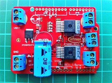
Out of the package, the board looks very well made and of high quality. There are however a few things that immediately drew my attention:

  • no headers on the board or in the box
  • a huge vertically mounted capacitor
  • no (screw) terminals, but instead big ring shaped pads

imageimage

Top and bottom view of the shield


No headers


This was already the case with the RGB LED Shield. My main problem with this is that you cannot start using the shield right away. If you have anticipated for the missing headers, the only remaining task is to solder them on. Else, you're stuck with an unusable shield until you are able to find a fitting pair of headers, which would probably delay you a day or two.


The fact that no headers are soldered on does give you the option to choose your own header type though: stackable, long, short, ... Whatever type suits your needs.


My suggestion remains the same as last time: include a pair of tall stackable headers in the box, preferably even soldered on.


Huge capacitor


The huge capacitor in the middle of the board really sticks out: about 25mm! One of the advantages of the BTN8982TA, is that it has very low board space consumption for the features it offers. I personally feel the capacitor obsoletes that advantage completely. It also prevents other shields to be stacked on top of this one, which seems like a big problem as other shields with displays or prototyping areas require to be on top.


Couldn't the capacitor have been put on its side ?


No (screw) terminals


One of the things I liked very much about the RGB LED Shield, were the screw-less terminals for both the power supply and the RGB LED strip. I was expecting something similar for this shield, but instead found big ring shaped pads. This will require soldering as opposed to the terminals, which makes it less practical for testing different types of motors and power supplies.


Is there a specific reason (except cost), why pads would be better than (screw) terminals ?


Software


I was looking for some sample code to use the shield with an Arduino, but I couldn't find any!


Not on the Infineon or E14's pages on the shield:

  • Infineon DC Motor Control Shield for Arduino
  • Boards and Shields for Arduino - Infineon Technologies


Unfortunate, but not a disaster as the shield seems easy enough to control.


This is the test sketch I came up with for testing:


First tests


There are two tests I wanted to perform using the motors I had at hand:

  • half-bridge configuration: controlling two unidirectional DC motors
  • H-bridge configuration: controlling a single bidirectional DC motor


But first ... finding a set of suitable headers to be able to use the shield and make some practical modifications.


Headers


I've ordered tall stackable headers for Arduino, but it will take some days until they get here. In the mean time, I've been experimenting with what I had at hand.


The first tests was to use different size male headers with an Arduin UNO. Using the typical size male headers, there was contact between the shield's VBAT connector and the UNO's USB port, which would create a very nasty short circuit. With a different size male headers the problem was resolved for the UNO.


imageimage

Testing different size headers to avoid contact between shield and USB port on the UNO


The next test was about finding suitable headers for the YUN. The Arduino YUN has a vertically mounted USB port and an ethernet port, which are sure to cause problems as they are taller than the UNO's USB port. The tall headers working for the UNO were too short for the YUN and had to be combined with intermediate female headers.


imageimage

Finding an appropriate combination of headers for the YUN


I'll be posting an update as soon as I receive the tall stackable headers I've ordered. In the mean, this will have to do image


image UPDATE: Extra tall stacking headers have arrived! The clearance for the YUN is just enough, I did put some tape on the bottom of the shield to avoid direct contact. With the capacitor on its side, it is possible to plug in another shield on top of the motor shield, although it should have long headers.


imageimage

Motor shield with extra tall stacking headers


Modifications


There are two modifications I made, based on the feedback given during my first observations: laying the capacitor on its side and using screw terminals.


image

Screw terminals and capacitor on its side


Single bidirectional motor


To use a single bidirectional motor with the shield, following steps were taken:

  • connect the motor to OUT1 and OUT2
  • connect a power supply (I used 12V/2A)
  • set INH1 and INH2 to HIGH
  • use IN1 for direction 1, IN2 for direction 2


Two unidirectional motors


To use a two unidirectional motors with the shield, following steps were taken:

  • connect the motor 1 to OUT1 and GND, motor 2 to OUT2 and GND
  • connect a power supply (I used 12V/2A)
  • set INH1 and INH2 to HIGH
  • use IN1 to control motor 1, IN2 for motor 2


Demo


Here's a video of the different modes in action:


You don't have permission to edit metadata of this video.
Edit media
x
image
Upload Preview
image


  • Sign in to reply

Top Comments

  • Jan Cumps
    Jan Cumps over 11 years ago in reply to shabaz +3
    It is certainly a nice design. The heat management is a school example. If you have the board in your hands, you have to contain yourself or you start drooling - it's done that well. But on the other side…
  • mcb1
    mcb1 over 11 years ago in reply to fvan +3
    Frederick Nice review and great timing. The price break makes it a very good choice for high power applications (which I have a use for). The stackability I think is for your small robot ... but then you…
  • fvan
    fvan over 11 years ago +3
    Updated the post with some pics of the shield with extra tall stacking headers!
  • DAB
    DAB over 11 years ago

    Great review,


    I liked your stacked pin solution to put the board higher.

    I think they intended the boards to be mounted remotely from the MCU using cables, based upon the layout.


    DAB

    • Cancel
    • Vote Up +2 Vote Down
    • Sign in to reply
    • More
    • Cancel
  • fvan
    fvan over 11 years ago in reply to shabaz

    I totally agree, the board is beautiful and looks well designed (I say "looks" because I'm no expert image).


    The feedback will probably vary depending on who's working with it.

    I'm more of an integrator myself, and until now I've been using off the shelf components to build projects. When I get a board like this, even if it is labeled as an evaluation board, I will try to use it in a project and bump into more practical issues. Issues which might not have been taken into account because the board's purpose is to evaluate the functionality of the components on it, not to be used in a project.

    Someone getting this board for the sake of evaluation and ultimately creating a design around those components will probably have completely different feedback.


    A question that comes to mind is then: did it have to have the Arduino shield form if meant as an evaluation board? If you label it a "shield", people are bound to try and get it on an Arduino image

    • Cancel
    • Vote Up +2 Vote Down
    • Sign in to reply
    • More
    • Cancel
  • Jan Cumps
    Jan Cumps over 11 years ago in reply to shabaz

    It is certainly a nice design. The heat management is a school example. If you have the board in your hands, you have to contain yourself or you start drooling - it's done that well.

    But on the other side is presented as an Arduino shield.


    I get your comments on replacing the caps - and that is also what fvan and myself seem to have done in parallel without knowing from each other.


    And the source code that is advertised in the quick start guide is not there (or at least I cant find it). That's the first thing you look for when evaluating.


    I am going to use this board big time. It's a winner with very capable ICs on them. But the story could have been so much more beautiful without additional costs on Infineon's side.

    For the same money, they could have made a slightly smaller board, with the connectors better placed and a different cap.

    On the other hand I'd also like to give them kudos for that cap. It's a nice one from Vishay.


    The picture isn't black or white, as always image

    • Cancel
    • Vote Up +3 Vote Down
    • Sign in to reply
    • More
    • Cancel
  • shabaz
    shabaz over 11 years ago in reply to clem57

    Hi!


    Probably 'Arduino' is a loose 'standard' if that. The Arduino bit is just to ensure people know what to expect in terms of interface pins and a convenient way to provide source code if needed.

    This board is really just to evaluate the motor controller IC for automotive purposes, and so doesn't need to overly play friendly with boards beyond providing the basic interface. The capacitor is a high voltage (50V) part to be compatible with most motors, but can be replaced with (say) a low-profile 16V one if needed, if another board needs to be stacked on top. The more expensive part they have fitted can then be kept for other needs!

    I personally think the board is quite well designed*, since I can connect up test leads easily using the 4mm holes. By the way, the board will fit many Freescale FRDM boards as-is, with normal sized headers, so even if jumper leads are not used, it will fit some microcontroller boards.


    * Just a personal opinion, everyone will have different needs however.

    • Cancel
    • Vote Up +2 Vote Down
    • Sign in to reply
    • More
    • Cancel
  • jw0752
    jw0752 over 11 years ago

    Hi Frederick, Your review brings to mind something that has bothered me throughout my career as a service technician. I have found myself between the designers, who did not bother to consult with their market, and the end user who wanted me to fix equipment that was not properly designed . This board appears to an excellent example of a lack of communication between the designer and the end user. How difficult would it have been to ask someone like You or Shabaz for some insights before making the board. I know that there is no way to make everyone happy and each change has its own set of side effects but the problem with the capacitor alone makes it quite clear that the designer did not understand how the board would be likely used. Thanks for your review and insights I always enjoy learning from you guys.

    John

    • Cancel
    • Vote Up +1 Vote Down
    • Sign in to reply
    • More
    • Cancel
<>
element14 Community

element14 is the first online community specifically for engineers. Connect with your peers and get expert answers to your questions.

  • Members
  • Learn
  • Technologies
  • Challenges & Projects
  • Products
  • Store
  • About Us
  • Feedback & Support
  • FAQs
  • Terms of Use
  • Privacy Policy
  • Legal and Copyright Notices
  • Sitemap
  • Cookies

An Avnet Company © 2026 Premier Farnell Limited. All Rights Reserved.

Premier Farnell Ltd, registered in England and Wales (no 00876412), registered office: Farnell House, Forge Lane, Leeds LS12 2NE.

ICP 备案号 10220084.

Follow element14

  • X
  • Facebook
  • linkedin
  • YouTube