This and other great measurement tips and tricks can be found on the General Purpose Electronics Test Equipment Blog
Monday, February 13, 2012
Simulating High Bandwidth Power Supply Transients
A power supply transient can be defined as an unintended variation of the supply’s amplitude or current. Example terms that refer to supply transients include power surge, spikes, dropouts, interrupts, etc. Power supply transients are caused by things like a sudden sharp load change or when external energy is coupled into the supply, such as when a lightening strike occurs near the supply.
Simulating power supply transients is needed to ensure the device will work to spec in its intended operating environment and ensure it is reliable. Example applications for power supply transient testing is in automotive, aircraft, and satellite electronics. In this blog post will look at a low cost solution for simulating high bandwidth power supply transients using general purpose test equipment and some simple analog circuitry.
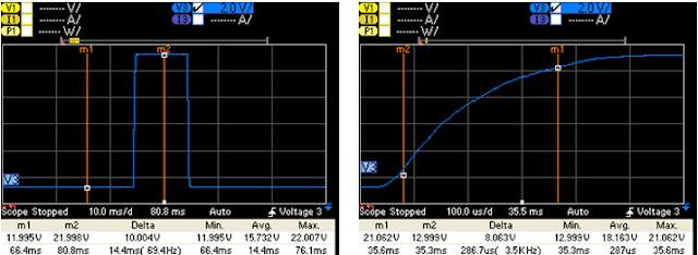
With modern high performance power supplies, transients with rise or fall times as fast as ~ 1ms can be simulated. The below images show a captured 10 V transient pulse on top of a 12 VDC level created with Keysight's N6705B DC Power Analyzer. You can see the measured rise time of the pulse is ~ 300 us.
To simulate power supply transients or power arbitrary waveforms with rise and fall times less than 300 us you can use the below solution, which we will call the Active Variable Resistive solution or AVR for short.
From the above AVR schematic, the two DC sources and the waveform generator can be implemented with general purpose test equipment. The MOSFET Switches and Choke are implemented using basic circuit components and should be chosen based on power levels and other considerations that we will discuss.
To go through the AVR system’s theory of operation lets use a simple example transient. Lets say we have a 10 V nominal DC power supply level powering our DUT (load) and we want to create a 10 V transient pulse with a 1 ms pulse width on top of our power supply level.
To start we would set DC source 1 to a 10 V level to serve as our nominal DC power supply level. The waveform generator would be set to a negative voltage value, like -5V, to turn on the P-type MOSFET switch so it acts as a short. In turn the negative voltage from the waveform generator would ensure the N-type MOSFET switch is reversed bias or off. Since the waveform generator’s low is floating, it is tied to the same node as the high of the load so it is at the same potential as the sources of the MOSFETs which are also connected to the same node as the load high. The choke is added to increase the impedance to ground when a transient is generated since there is a small amount of capacitance between the waveform generator’s low and ground. DC source 2 is set to 20 V, but no current is flowing out of it because the N-type switch is off. The current condition of the AVR system is DC source 1 is supplying power to the DUT at 10 V. To create the transient pulse we program the waveform generator for a single 1 ms pulse. The amplitude of the pulse should be enough to fully turn on the N-type switch, for this example we will say 5 V. When the pulse is triggered it will turn the N-type switch on and the P-type switch off. DC source 2 will quickly pull the load node up to 20 V and DC source 1 is effectively removed from the DUT. After 1 ms the waveform generator’s output will go low again and turn off the N-type switch and turn on the P-type switch. This removes DC source 2 from the load and puts DC source 1 back in the load circuit. At this point we have generated our 10 V transient pulse on top of our 10 V power supply level and we are now back at our initial conditions.
To generate a negative pulse with the AVR we would set DC source 2 for the nominal DC level and set DC source 1 to the bottom level of the interrupt, which could be any level between 0 V and the nominal DC level. Set the waveform generator so that the initial condition of the N-type switch is on and the P-type switch is off. Then, using the waveform generator, send a negative pulse to toggle the switches to create the interrupt. To create more complex power waveforms you would use the MOSFETs as variable resistors instead of switches. In this case ensure you use high power MOSFETs and heat dissipation as needed. Also for more complex waveforms a two channel waveform generator would be ideal so the two MOSFETs are not tied to the same waveform.
I implemented the solution using the following test equipment and components:
•DC source 1: N6705B DC Power Analyzer with N6762A Module
•DC source 2: N6705B DC Power Analyzer with N6762A Module
•MOSFET Switches: multiProductLinkSi4410BDY and Si4925BDY
•Waveform Generator: 33522A Fg / Awg
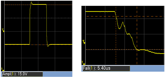
Using the implemented AVR solution I created the below example 15 V 1 ms transient pulse on a 10 VDC level. The first scope shot shows the whole pulse and the second shows the rise time. Both rise and fall times were less than 6 us.
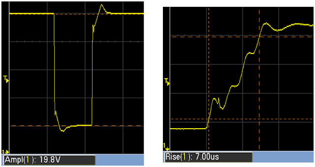
The pulse transient was generated into a 10 Ohm load with a 0.1 uF, 1 uF, and 10 uF capacitors in parallel. This was done to simulate a real world DUT supply input that presents a low impedance to ground for AC signals. Below is an interrupt created with the solution into the same load. The DC level is 25 V. The interrupt pulse is 20 V with a width of 500 us. The resulting fall and rise time of the interrupt is about 7 us.
Simulating power supply transients with a modern high performance power supply allows you to create waveforms with rise and fall times as fast as 300 us. To achieve higher bandwidths a high cost power system is typically employed by standards and quality labs. In this post we discussed and demonstrated a low cost alternative solution for creating higher bandwidth power supply transient waveforms right on the bench. If you have any questions, comments, or add-ons to this post please leave them in the "comments" section below.
Click here for more information on the N6705B DC Power Analyzer


