


Introduction
This blog contains my thoughts on the Coeur CST connector samples sent to me as detailed in this original blog;
rscasny has already provided an insight into the connection system in the blog Avoiding Connector Failures with Multiple Beam Floating Contact Design, so my blog will be more of a pragmatic approach to the connection system and the sample pack provided.
The sample pack provided consisted of two male pins and three female sockets from their 200A connector range, which has a nominal 8mm diameter.

Both male pins are of a press fit design, with one already pressed into a connection plate and the other provided just as the pin, ready to be pressed into something like a busbar. Two of the female sockets have the floating design, one is a press fit and the other is surface mount. The final female socket does not have a floating mechanism and is also a surface mount fit.
The sample pack only forms part of the 200A range, which appears to have the largest number of options. Unique to this range is a crimp connector and a plug and socket housing to provide an insulated connector. This item however, does not appear to have the floating design.

A cross section of the floating design, shows how the centre section is allowed to move within the outer connection, with the required pressure for the electrical conductivity, maintained by a ripple style washer on both sides of it (arrowed in the picture).

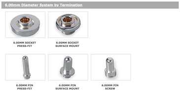
The Coeur CST system also include a 3.4mm diameter range rated to 75A and a 6.0mm range rated to 140A. These two ranges do not have as many items to them as the 200A range does. They do have a surface mount male pin, that does not appear to be present in the 200A range. Like the 200A range, the 140A range also has a screw fit male pin, but this is not included in the 75A range. All three ranges are rated up to 600V.

I am not sure why each of the ranges has different options, some of it may be down to machining limitations. However, this did seem a little strange to me, as I could utilise some of the options in the 200A range in the lower current ranges. The connectors appear to have been developed for use with the Triton busbar system also available from Molex, and this may also been a reason for the different options available.
Prices for the components in the UK seems to range from £2.00 to £3.50 for the pins, £4.00 to £7.00 for a socket without float and £7.00 up to £14.00 for a socket with float. These are prices for individual items and more competitive pricers were available for bulk orders.
The quality of the sample that arrived seems to be high. The male pins and female housings are coated in a silver-nickel plating. The contact springs within the female housings are gold-nickel plated. The washer in the float mechanism is also of the same gold-nickel plating, but these are not visible without cutting open the connector.
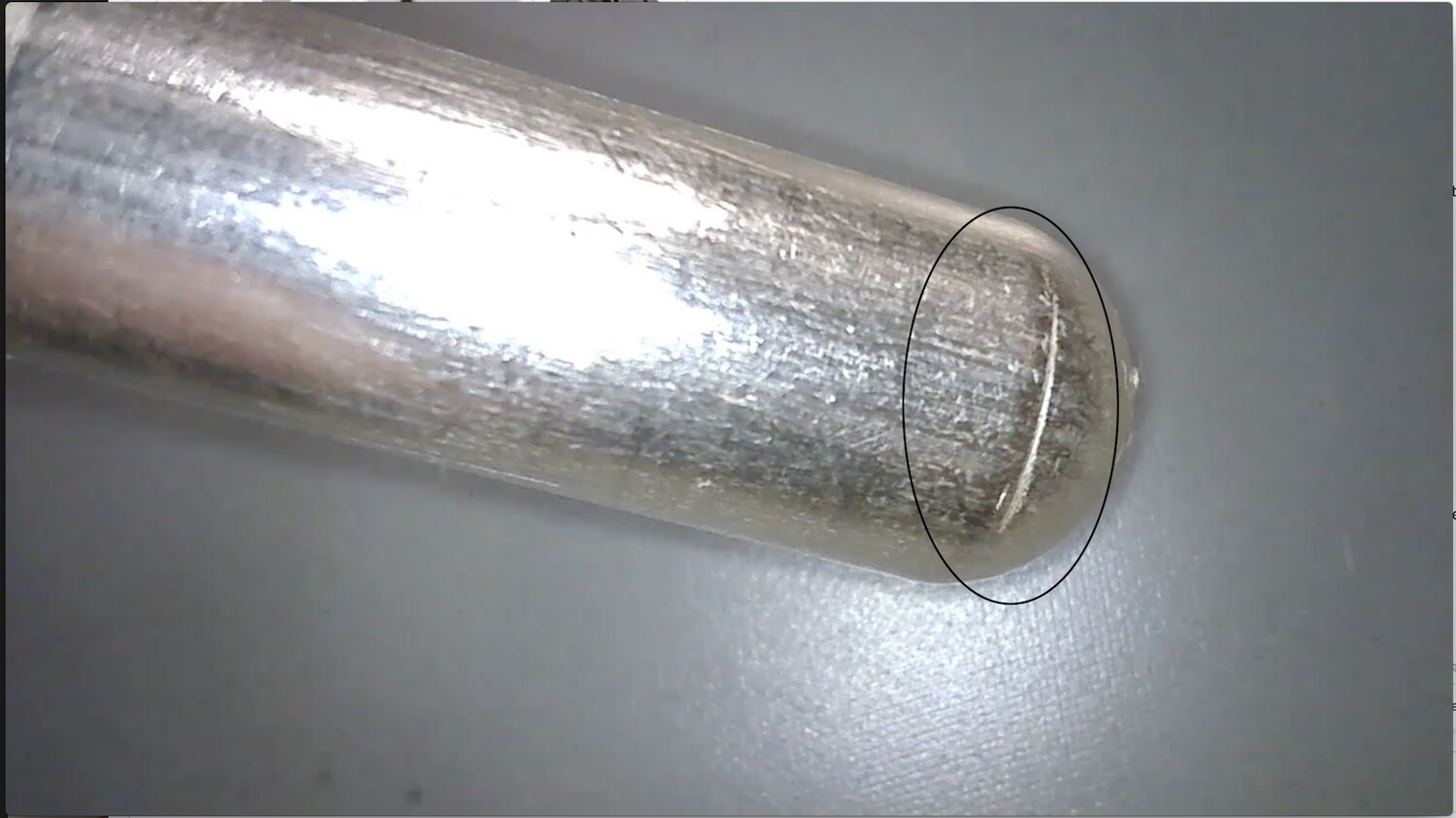
Inspection under a microscope did reveal a score in one of the male pins toward the tip, so I do not believe that it would be detrimental to the reliability of the connector.
As the connectors are mated and un-mated, a scoring pattern starts to appear on the male pins and particles of the plating appear on the female leaf springs as seen below.

The manufacturer's specifications give the number of mating cycles as greater than two hundred, so this connector is not meant for every day use. Neither is it intended to break the load current, the load would need to be switched out before unplugging these connectors. In contrast a standard IEC 60320 C13 connector (below) will have a minimum of 3000 mechanical mating cycles.

Comparison to other floating designs.
My knowledge of floating connector designs is basically from removable switchgear cassettes and fuse switches that employ a connector system to allow a section of the apparatus to be removed for either maintenance or isolation purposes. These designs tend to be a three piece design employing a floating spring loaded section between two connection bosses that are attached to the busbar and apparatus. Some are circular in design as seen on the left and others offer a connection between two flat bosses as seen on the right.


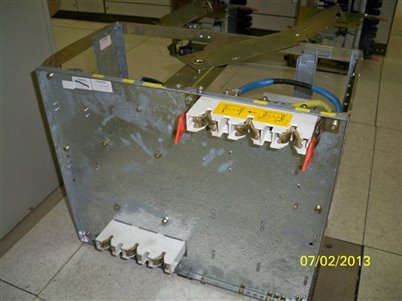
Other designs employ an over large tension spring to take up slack between the cassette mechanism and its housing, as shown for the 400V motor feeder cassette below.

A similar design is employed within fuse-switch isolators. Below is the base plate removed from the isolator, with the floating contact connected to the base plate contact on the bottom and the moving fuse carrier contact at the top. It can be seen that the floating contact needs to be connected to both contacts to make it stable.

These designs allow for thermal expansion and contraction of the copper conductors created by the cycling of the loads. As with the Molex CST connectors whilst they can be opened when live, they do not have the ability to break any significant current, so the cassettes have interlocking mechanisms that prevent them from being removed whilst the main isolator is switched on.
These designs differ significantly from the design offered by Molex. The Molex connector is a much more compact design, it would seem to be more robust than some of the existing designs Have utilised, that can become bent and damaged through too much mis-alignment. Failure of the spring also renders the contact useless, where as the Molex design offers physical protection for the wafer spring providing the float.
The downside for me with this type of application is that the housing are subject to type approval to IEC standards, so the use of connectors for this application is very much in the hands of well established manufacturers.
Project Options
Smaller versions of the connectors provided could look useful for applications such as my current amplifier, that has swappable coils. The ad hoc nature of the build means that misalignment of connectors is quite likely, as depicted below. Whilst the black socket is aligned with the pin on the coil, a little misalignment can be seen between the red socket and the other pin of the coil.

The screw type pin could be made to fit very easily on the coil formers and replace the existing 4mm pins. Mounting the sockets onto the amplifier would be a little more challenging. The socket first has to be mounted into an electrical conductor to allow connection into the circuit, this in turn would need mounting into an insulator to stop it shorting to the other connector and / or the chassis. Not insurmountable, but is likely to get messy.
The Molex website contains dimensional drawings for each of the contacts so the necessary engineering tolerances can be established for mounting the press fit connectors. They also have a useful application document for the range that goes through installing the press fit and surface mount connectors, I have attached to this blog.
For the press fit a 0.02mm tolerance is recommended on the hole size as seen below. This, I imagine, would be quite taxing to manufacture without quality engineering cutters and machines.

The surface mount versions are recommended to be soldered within a reflow oven using solder paste as per below. Again, probably something outside of your average maker.

All the documentation is available from the Molex website on the link below, an then selecting the desired connector.
It doesn't really seem to be beneficial to attempt the above project, so in order to make some use of the connectors, I plan to make up a rig to test the mating cycle. I propose a linear actuator with a load cell at one end, so that the mating force can be measured. I cannot quite fathom out how to make the rig to also measure the un-mating force, unless I use two load cells. I then propose to measure the connector resistance each mating cycle using the 4-wire method.
This does seem like a good project to use the DAQ970A in a control environment, to operate the linear actuator, record the force and then measure the resistance, before un-mating the connector using the linear actuator. To do this will require a DAQM903A actuator card, that is a little difficult to get hold of in the UK, with out paying an elevated price. However, it will take me some time to get the connectors mounted into a connection system. If I can make the connection system strong enough, I should also be able to inject 100A through the connector and look at the thermal pattern, before and after the tests.

This is going to take me a while to source all the parts I need and carry out the manufacturer of the frame for the actuator and the connector, but over a period of time, it seems like a more achievable option.
The following video shows the resistance of the connectors being tested with a source measurement unit.
Conclusion
The Molex Coeur CST, seems to be a novel approach to managing alignment of connectors, that can undoubtedly put strain on connections and lead to premature failure. They come in a number of different options, that is also dependent upon their rating, and a cost that restricts them to more specialist applications.
As well as allowing for movement during the connection process, they will also allow for movement through thermal expansion and contraction, which will certainly occur at the 200A rating of the connector.
Whilst they are a high quality connector, their use would seem to be more inline with commercial manufacturing, or a very serious maker with enough time and knowhow to install them correctly.
| 200A Range Application Document.pdf | |
| 200A Press Fit Connector Engineering Drawing.pdf |


Top Comments