


Table of Contents
Introduction
This blog was inspired by the current Spring Clean Competition where you take an old electronics project and complete it. Here, I’ve decided to finally put an unused development board I ordered back in 2019 to good use.
The development board in question is the NXP LPCXpresso55S69 / LPC55S69-EVK. The board uses a LPC55S69 dual core Arm Cortex-M33 microcontroller running at up to 150 MHz with up to 320 KB of on-chip SRAM, and up to 640 KB on-chip flash.
As the block diagram below illustrates, the LPC55S69 contains a wide range of features. One feature that jumped out at me was the multi-channel 16-bit ADC with sampling rates up to 1.0 Msamples/s. The ADC also has a dedicated input channel for an on-chip temperature sensor that is mapped on channel 26. To purchase a dedicated 16-bit ADC IC is expensive on it's own, so this dual-core MCU is worth looking at.

The board itself has an interesting layout, with the option to use either Arduino R3 compatible shields, or Mikroe click boards. Another interesting feature on this board is the inclusion of a Cirrus Logic (Wolfson) WM8904 audio codec with line input (for microphone) and output (for speaker) jacks, and an NXP MMA8652FCR1 accelerometer with I2C interface. Other peripherals include a USB host, an RGB LED and four input buttons.

When I first ordered this board, the documented process to get started was to download the standalone MCUXpresso IDE and use the MCUXpresso SDK, once downloaded, to build your applications.
This has subsequently changed and there is now the option to use the VSCode IDE together with the MCUXpresso extension. This option also allows you to use either Zephyr RTOS or the MCUXpresso SDK. Further details can be found here: https://community.nxp.com/t5/Zephyr-Project-Knowledge-Base/Zephyr-Knowledge-Hub/ta-p/2008548
Key concepts about the Zephyr RTOS ecosystem
I am not going to follow these options in this blog. Instead, I’m going to rely on the Zephyr project’s own getting started guide to demonstrate some key concepts about the Zephyr development framework.
The first concept to grasp is that unlike, for example, Mbed or Arduino, Zephyr-RTOS does not require an IDE. You can simply create your C/C++ (or Rust) code using any text editor and then use the command line based interface (CLI) from within an initialised workspace folder to build, flash and debug your project. This is revealed in the setup process (see next section). Of course, using something like VSCode does make life a whole lot easier.
The second concept to grasp is that unlike most IDE’s for embedded code development, you cannot readily develop a Zephyr based application outside of a defined workspace. Typical project layout typologies that work within Zephyr are described here: https://docs.zephyrproject.org/latest/develop/west/workspaces.html#topologies-supported
The topology that seems to work well for me is as follows:

Inside my defined workspace (usually I name this “zephyrproject”), I would typically create a folder called “my_apps” or “application” and then create various project folders inside that folder.
The third concept to get your head around is that all application source code (as found in the src folder) is hardware agnostic. In each project folder, there are specific files that are required in each and every project, namely:
- CMakeLists.txt
- prj.conf (project specific settings for drivers. E.g. enabling the GPIO driver is done here)
- "src" folder for main.c
- project folder sample.yaml file. This text file describes the nature of the project.
- a "boards" folder if your project is being developed for different boards. This folder will include config (driver info) and overlay (hardware interface) settings specific for a board.
So you will never find any of these type of declarations in your Zephyr project’s source code:


Instead, these interface definitions are all abstracted out of the application and placed in either an overlay or device tree structure file as well as the project configuration files.
Interfacing with sensors is the fourth, and potentially the most challenging, concept to address. Unlike the ad-hoc methods common in MCU SDKs, Zephyr provides a prescribed sensor framework. This framework outlines requirements like polling and trigger mode, and specifies how sensor data is read using defined functions.
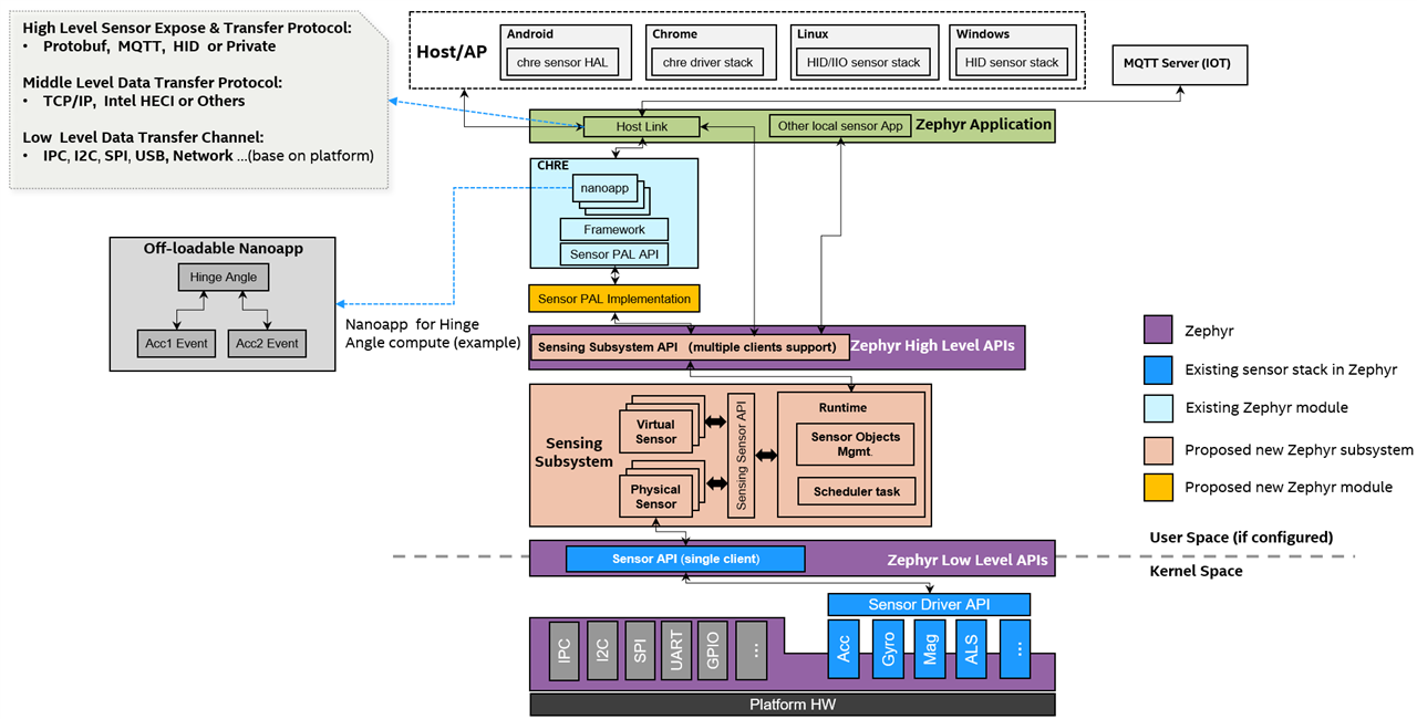
image source: https://docs.zephyrproject.org/latest/services/sensing/index.html
Anyway, the best way to illustrate these concepts is through examples, so let’s start with the Zephyr-RTOS setup.
Installing Zephyr-RTOS on your computer
I've created a flow chart to show you what's involved. As mentioned, it does not involve installing an IDE.

The main pain-point, in my opinion, is installing the minimum required version of Python. Zephyr has now pushed this to Python 3.12 for the up and coming version 4.2. This requires a few extra steps if, like me, you were still using Python 3.10. To illustrate what's involved, I've created a video that captures the installation process up to the "install Zephyr SDK".
I've kept the "Install Zephyr SDK" step separate to highlight the location of where it installs the SDK and some of the options you have at your disposal - it's not explicitly explained in the getting started guide (hint: it's not installed in the Zephyr directory). The default location is your root directory (well for Linux anyway).

Once you have the SDK installed you are good to go.

Blinky and beyond (looking at some of the samples provided)

source: https://docs.zephyrproject.org/latest/samples/index.html
There are certainly a wide range of examples available on Zephyr (within the Zephyr directory inside your workspace there is a "samples" folder, which contains all the latest examples). Unfortunately, the documentation for these examples are not provided as tutorials, so some examples are easier to understand than others. Hopefully my explanations about the examples I selected to test out will help you understand how it all works.
For starters, I find the best way to work with any example is to copy the folder and place within your own "my_apps" folder inside your workspace. Then you can experiment away. This is much better than simply using the command: west build -b reel_board samples/basic/blinky, which builds the project for you inside the Zephyr folder.
Let's start with Blinky
The example's README.rst reveals much (if you struggle with the README refer to the online documentation, which is a tad better):
.. zephyr:code-sample:: blinky
   :name: Blinky
   :relevant-api: gpio_interface

   Blink an LED forever using the GPIO API.

Overview
********

The Blinky sample blinks an LED forever using the :ref:`GPIO API <gpio_api>`.

The source code shows how to:

#. Get a pin specification from the :ref:`devicetree <dt-guide>` as a
   :c:struct:`gpio_dt_spec`
#. Configure the GPIO pin as an output
#. Toggle the pin forever

See :zephyr:code-sample:`pwm-blinky` for a similar sample that uses the PWM API instead.

.. _blinky-sample-requirements:

Requirements
************

Your board must:

#. Have an LED connected via a GPIO pin (these are called "User LEDs" on many of
   Zephyr's :ref:`boards`).
#. Have the LED configured using the ``led0`` devicetree alias.

Building and Running
********************

Build and flash Blinky as follows, changing ``reel_board`` for your board:

.. zephyr-app-commands::
   :zephyr-app: samples/basic/blinky
   :board: reel_board
   :goals: build flash
   :compact:

After flashing, the LED starts to blink and messages with the current LED state
are printed on the console. If a runtime error occurs, the sample exits without
printing to the console.

Build errors
************

You will see a build error at the source code line defining the ``struct
gpio_dt_spec led`` variable if you try to build Blinky for an unsupported
board.

On GCC-based toolchains, the error looks like this:

.. code-block:: none

   error: '__device_dts_ord_DT_N_ALIAS_led_P_gpios_IDX_0_PH_ORD' undeclared here (not in a function)

Adding board support
********************

To add support for your board, add something like this to your devicetree:

.. code-block:: DTS

   / {
   	aliases {
   		led0 = &myled0;
   	};

   	leds {
   		compatible = "gpio-leds";
   		myled0: led_0 {
   			gpios = <&gpio0 13 GPIO_ACTIVE_LOW>;
                };
   	};
   };

The above sets your board's ``led0`` alias to use pin 13 on GPIO controller
``gpio0``. The pin flags :c:macro:`GPIO_ACTIVE_HIGH` mean the LED is on when
the pin is set to its high state, and off when the pin is in its low state.

Tips:

- See :dtcompatible:`gpio-leds` for more information on defining GPIO-based LEDs
  in devicetree.

- If you're not sure what to do, check the devicetrees for supported boards which
  use the same SoC as your target. See :ref:`get-devicetree-outputs` for details.

- See :zephyr_file:`include/zephyr/dt-bindings/gpio/gpio.h` for the flags you can use
  in devicetree.

- If the LED is built in to your board hardware, the alias should be defined in
  your :ref:`BOARD.dts file <devicetree-in-out-files>`. Otherwise, you can
  define one in a :ref:`devicetree overlay <set-devicetree-overlays>`.
As per the markdown README text, the magic happens because there’s an “LED configured using the ``led0`` devicetree alias”.
This is also defined on line 15 inside main.c: #define LED0_NODE DT_ALIAS(led0)
And then tied to the data structure gpio_dt_spec on line 21: static const struct gpio_dt_spec led = GPIO_DT_SPEC_GET(LED0_NODE, gpios);
/*
 * Copyright (c) 2016 Intel Corporation
 *
 * SPDX-License-Identifier: Apache-2.0
 */

#include <stdio.h>
#include <zephyr/kernel.h>
#include <zephyr/drivers/gpio.h>

/* 1000 msec = 1 sec */
#define SLEEP_TIME_MS   1000

/* The devicetree node identifier for the "led0" alias. */
#define LED0_NODE DT_ALIAS(led0)

/*
 * A build error on this line means your board is unsupported.
 * See the sample documentation for information on how to fix this.
 */
static const struct gpio_dt_spec led = GPIO_DT_SPEC_GET(LED0_NODE, gpios);

int main(void)
{
	int ret;
	bool led_state = true;

	if (!gpio_is_ready_dt(&led)) {
		return 0;
	}

	ret = gpio_pin_configure_dt(&led, GPIO_OUTPUT_ACTIVE);
	if (ret < 0) {
		return 0;
	}

	while (1) {
		ret = gpio_pin_toggle_dt(&led);
		if (ret < 0) {
			return 0;
		}

		led_state = !led_state;
		printf("LED state: %s\n", led_state ? "ON" : "OFF");
		k_msleep(SLEEP_TIME_MS);
	}
	return 0;
}
But where is led0 defined, in terms of attaching it to an actual GPIO pin number, you may ask.
Well, before I reveal the location inside your zephyr project workspace, let me point out an important online reference, which I find myself returning to very frequently. It’s found at the bottom on the Zephyrproject’s homepage (alternatively you look inside the Zephyr folder). A video captures this best:
Knowing these details within the board (dtsi & dts) files will save you a stack of time understanding the interfaces available by default, versus ones you’ll need to customise yourself. It’s vital that you study to these files when moving on to a new board.
For our LPC55S69-EVK board, we have three LED's (representing the RGB LED) defined inside the lpcxpresso55s69.dtsi file. The GPIO definitions match section 7.4 (RGB User LED) if our EVK documentation (UM11158-1.PDF), which states "The LEDs in this device are controlled by LPC55Sxx ports P1_4 (Blue), P1_6 (Red), P1_7 (Green) with the LEDs being illuminated when the respective LED is pulled low."

As you can see the status for these LED's are marked as disabled.
These LED's are then marked as "okay" when you choose to use CPU0, as seen in the lpcxpresso55s69_lpc55s69_cpu0.dts file:

So, now that we know the default device tree structure for our board, let's test out blinky by building and flashing our board using West.
Now suppose we want to blink an LED which is attached to a different GPIO, altogether. How do we do that. Well, it's rather straightforward.
First, we need to create an overlay file and save it using a specific name for our board. Namely, lpcxpresso55s69_lpc55s69_cpu0.overlay.
Then it's as per the blinky documentation where we define which GPIO we intend to use.
The GPIO pin numbering is listed in the lpcxpresso55s69.dtsi file.

There are actually two formats available for defining which GPIO we want to use. If we chose say Arduino-R3 D7, we can use either of these formats:
gpios = <&gpio1 9 GPIO_ACTIVE_HIGH>;
gpios = <&arduino_header 13 GPIO_ACTIVE_HIGH>;
/ {
     aliases {
             led3 = &myled3;
     };

     leds {
             compatible = "gpio-leds";
             myled3: led_3 {
                     //gpios = <&gpio1 9 GPIO_ACTIVE_HIGH>;
                     gpios = <&arduino_header 13 GPIO_ACTIVE_HIGH>;
             };
     };
};
Now that we have an led3 defined we can modify our main.c code. We will also change led0 to led1 inside our main.c, for good measure.
/*
 * Copyright (c) 2016 Intel Corporation
 *
 * SPDX-License-Identifier: Apache-2.0
 */

#include <stdio.h>
#include <zephyr/kernel.h>
#include <zephyr/drivers/gpio.h>

/* 2000 msec = 2 sec */
#define SLEEP_TIME_MS   2000

/* The devicetree node identifier for the "led1" alias. */
#define LED1_NODE DT_ALIAS(led1)
#define LED3_NODE DT_ALIAS(led3)

/*
 * A build error on this line means your board is unsupported.
 * See the sample documentation for information on how to fix this.
 */
static const struct gpio_dt_spec led1 = GPIO_DT_SPEC_GET(LED1_NODE, gpios);
static const struct gpio_dt_spec led3 = GPIO_DT_SPEC_GET(LED3_NODE, gpios);

int main(void)
{
	int ret;
	bool led1_state = true;
	bool led3_state = true;

	if (!gpio_is_ready_dt(&led1) || !gpio_is_ready_dt(&led3)) {
		return 0;
	}

	if(gpio_pin_configure_dt(&led1, GPIO_OUTPUT_ACTIVE) < 0 || gpio_pin_configure_dt(&led3, GPIO_OUTPUT_ACTIVE) < 0) {
		return 0;
	}

	while (1) {
		ret = gpio_pin_toggle_dt(&led1);
		if (ret < 0) {
			return 0;
		}
		led1_state = !led1_state;
		printf("LED1 state: %s\n", led1_state ? "ON" : "OFF");

		ret = gpio_pin_toggle_dt(&led3);
		if (ret < 0) {
			return 0;
		}

		led3_state = !led3_state;
		printf("LED3 state: %s\n", led3_state ? "ON" : "OFF");

		k_msleep(SLEEP_TIME_MS);
	}

	return 0;
}
Here is the result:
I did notice one quirk with my board though. If I tried using led0 and GPIO D7, it did not work as expected. It appears that PIO1_6 (Red LED or D3) and PIO1_9 (D7) are mixed up somewhere.
Having a play with PWM
The next example I wanted to test was the blinky_pwm example. This uses a different API to drive the GPIO's.
The first check is to see if pwm_led0 is listed anywhere in the board's device tree.
Seems we are in luck:


After building and flashing here's the result:
But, hold on a minute. It's flashing blue not red. What's going on?
Yes, it appears we have a typo error in the board's device tree in that "red_pwm_led" should really be "blue_pwm_led".
To understand what's going on, we have to look at section 6 (Pinning information) of the LPC55S6x's datasheet. Here it shows that when using SCTimer, only PIO1_4 (Blue LED) works as an output. PIO1_6 and PIO1_7 can only be used as a PWM input with SCTimer.


Thankfully, CTimer2 is listed as being available as a PWM output to drive both the red and green LED's. So, let's give this a try.
First, we need an overlay file with the relevant info. Here I am going to use the red LED (PIO1_6).
/*
 * Devicetree overlay for the NXP LPCXPRESSO55S69 development board.
 * This overlay enables CTIMER2 to control the onboard RGB LEDs
 * via PWM, making it compatible with samples like fade_led.
 *
 * - Blue LED:  P1_4 -> CTIMER2_MATCH1
 * - Red LED:   P1_6 -> CTIMER2_MATCH1
 * - Green LED: P1_7 -> CTIMER2_MATCH2
 */

/ {
    /*
     * Aliases are created to provide a fixed name for each PWM-controlled LED.
     * The fade_led sample code uses these specific aliases ("pwm-led0", etc.)
     * to find the correct PWM channels.
     */
    aliases {
        /* Map to CTIMER2 channels 0, 1, 2 */
        pwm-0 = &ctimer2;
        pwm-led0 = &red_pwm_led;
		red-pwm-led = &red_pwm_led;
    };

    pwmleds {
        compatible = "pwm-leds";

        red_pwm_led: red_pwm_led {
            /* Mapped to CTIMER2 channel 1 */
            pwms = <&ctimer2 1 PWM_MSEC(20) PWM_POLARITY_NORMAL>;
            label = "Green PWM LED";
			status = "okay";
        };
    };
};

&sc_timer {
	status = "disabled";
};

/* Enable CTIMER2 for PWM functionality */
&ctimer2 {
    compatible = "nxp,ctimer-pwm";
    prescaler = <1>;
    clk-source = <0>;				// assuming this is main
    pinctrl-0 = <&pinmux_ctimer2_pwm_rgb>;
    pinctrl-names = "default";
    #pwm-cells = <3>;
    status = "okay";
};

/*
 * The pinctrl node is used to configure the pin multiplexing.
 * We need to switch the function of the LED GPIO pins from standard GPIO
 * to be outputs for the CTIMER2 peripheral.
 */
&pinctrl {
    /* A custom pinctrl group for our RGB LED configuration on CTIMER2. */
    pinmux_ctimer2_pwm_rgb: pinmux_ctimer2_pwm_rgb {
        group0 {
            /* Red LED - P1_6 */
			pinmux = <CTIMER2_MATCH1_PIO1_6>;
            slew-rate = "standard";
        };
    };
};
As shown, I have a ctimer2 object which I've made compatible to "nxp,ctimer-pwm". This means I have to comply with the requirements described in nxp,ctimer-pwm.yaml. These yaml files are typically stored inside the dts/bindings folder. The easiest way to find these files is to just do a file search.
# (c) Meta Platforms, Inc. and affiliates.
# SPDX-License-Identifier: Apache-2.0

description: NXP CTimer PWM

compatible: "nxp,ctimer-pwm"

include: [pwm-controller.yaml, pinctrl-device.yaml, base.yaml, "nxp,lpc-ctimer.yaml"]

properties:
  reg:
    required: true

  prescaler:
    type: int
    default: 1
    description: prescaling value

  clk-source:
    type: int
    required: true
    description: clock to use

  "#pwm-cells":
    const: 3

pwm-cells:
  - channel
  - period
  - flags
Well it works, but I'm not convinced I have this working perfectly, as the output seems to stop and does not switch back on immediately when the period decreases etc.
Anyway, as you can see, it does take effort to get to the bottom of things.
Interfacing with I2C sensors
To take my Zephyr-RTOS testing up a notch, I decided to try out some sensor examples.
I discovered that the accel_trig example is compatible with the onboard accelerometer. All that was needed was to define the type of accelerometer inside the board's config file.
So, within the project config file (prj.conf) we state that we with to use the sensor interface.
CONFIG_STDOUT_CONSOLE=y
CONFIG_SENSOR=y
CONFIG_CBPRINTF_FP_SUPPORT=y
Then within the lpcxpresso55s69_lpc55s69_cpu0.conf file we add more specifics about the sensor (here we state that we have a sensor which will work with the FXOS8700 library):
CONFIG_FXOS8700_TRIGGER_OWN_THREAD=y
CONFIG_FXOS8700_MODE_ACCEL=y
The I2C interface is already taken care of inside the board's device tree source files.
Then it's just a case of building and flashing the board using West.
So why does this work for multiple boards?
The key is in the use of standardised functions, such as sensor_sample_fetch(dev) to read data, and sensor_channel_get(dev, SENSOR_CHAN_ACCEL_XYZ, data) to parse the data. All sensor libraries require these two functions. This then allows you to right more generic application code.
I think this is a pretty good approach, although it makes it quite difficult to create your own sensor libraries.
In my next test, I went a step further. I discovered that there were some libraries available for the Grove I2C based RGB LCD display and for the Grove DHT20 temperature and humidity sensor. I then created my own application to display temperature and humidity data on the LCD screen. The background colour also changes when the temperature exceeds 30 degrees.
For this project we need an overlay file to define the sensor properties within our I2C object.
/*
 * Devicetree overlay for the NXP LPCXPRESSO55S69 development board.
 */

i2c_0: &flexcomm4 {
	status = "okay";
	compatible = "nxp,lpc-i2c";
	clock-frequency = <I2C_BITRATE_STANDARD>;
	#address-cells = <1>;
	#size-cells = <0>;

	dht20_sensor: dht20@38 {
		compatible = "aosong,dht20";
		reg = <0x38>;
	    status = "okay";
	    label = "Grove_DHT20";
	};

	glcd: glcd@3e {
		compatible = "seeed,grove-lcd-rgb";
		reg = <0x3e>;                           // equivalent to 0x7c>>1
	    status = "okay";
	    label = "Grove_LCD";
	};

};
Then we define our project config file (prj.conf):
CONFIG_STDOUT_CONSOLE=y
CONFIG_I2C=y
CONFIG_SENSOR=y
CONFIG_GROVE_LCD_RGB=y
CONFIG_LOG=y
CONFIG_SENSOR_LOG_LEVEL_DBG=y
CONFIG_CBPRINTF_FP_SUPPORT=y
And finally we create our application code inside main.c:
/*
 * Copyright (c) 2016 Intel Corporation.
 *
 * SPDX-License-Identifier: Apache-2.0
 */

#include <zephyr/kernel.h>
#include <zephyr/device.h>
#include <zephyr/drivers/sensor.h>
#include <zephyr/sys/printk.h>
#include <zephyr/sys/util.h>

#include <zephyr/drivers/misc/grove_lcd/grove_lcd.h>
#include <stdio.h>
#include <string.h>

const int colorR = 0;
const int colorG = 255;
const int colorB = 0;

const int colorR_HOT = 255;
const int colorG_HOT = 0;


static void process_sample(const struct device *dht20, const struct device *glcd)
{
	struct sensor_value temp, hum;

	/* clear LCD */
	char row[16];
	double my_temp, my_rh;

	if (sensor_sample_fetch(dht20) < 0) {
		printk("Failed to fetch sample for %s\n", dht20->name);
		return;
	}

	if (sensor_channel_get(dht20, SENSOR_CHAN_AMBIENT_TEMP, &temp) < 0) {
		printk("Failed to get temperature data for %s\n", dht20->name);
		return;
	}

	if (sensor_channel_get(dht20, SENSOR_CHAN_HUMIDITY, &hum) < 0) {
		printk("Failed to get humidity data for %s\n", dht20->name);
		return;
	}

	my_temp = sensor_value_to_double(&temp);
	my_rh = sensor_value_to_double(&hum);
	printk("Temperature: %.2f C, Humidity: %.2f %%\n", my_temp, my_rh);

	// change the background colour according to temperature
	if (my_temp > 30.0) {
		glcd_color_set(glcd, colorR_HOT, colorG_HOT, colorB);
	}
	else {
		glcd_color_set(glcd, colorR, colorG, colorB);
	}

	(void)memset(row, ' ', sizeof(row));
	glcd_cursor_pos_set(glcd, 0, 1);
	sprintf(row, "%.1f%cC RH:%.0f%c", my_temp, 223 /* degree symbol */, my_rh, 37 /* percent symbol */);
	glcd_print(glcd, row, strlen(row));

}

int main(void)
{
	const struct device *const dht20 = DEVICE_DT_GET(DT_NODELABEL(dht20_sensor));

	const struct device *const glcd = DEVICE_DT_GET(DT_NODELABEL(glcd));

	if (!device_is_ready(dht20)) {
		printk("DHT20 sensor device not ready\n");
		return 0;
	}
	printk("DHT20 sensor is ready\n");

	if (!device_is_ready(glcd)) {
		printk("Grove LCD not ready\n");
		return 0;
	}
	printk("Grove RGB LCD is ready\n");

	/* configure LCD */
	glcd_function_set(glcd, GLCD_FS_ROWS_2 | GLCD_FS_DOT_SIZE_LITTLE | GLCD_FS_8BIT_MODE);
	glcd_input_state_set(glcd, GLCD_IS_ENTRY_LEFT | GLCD_IS_SHIFT_DECREMENT);
	glcd_cursor_pos_set(glcd, 0, 0);
	glcd_print(glcd, "hello, DHT20!", 13);
	/* set the background colour */
	glcd_color_set(glcd, colorR, colorG, colorB);

	glcd_display_state_set(glcd, GLCD_DS_DISPLAY_ON);

	while (1) {
		process_sample(dht20, glcd);
		k_sleep(K_MSEC(2000));
	}
	return 0;
}
As you might see, inside main.c we link the sensors using these commands. Then from here the sensor interface is established via the standard functions (as described above).
const struct device *const dht20 = DEVICE_DT_GET(DT_NODELABEL(dht20_sensor));
const struct device *const glcd = DEVICE_DT_GET(DT_NODELABEL(glcd));
It's as simple as that.
Showcasing SPI using a TFT Display
My final test was using SPI. Here I decided to play with my TFT displays, and with Zephyr-RTOS this proved the most fun.
One of the first things I discovered is that the LVGL module, which comes standard with Zephyr was too big for the LPC55S69 MCU. So, I was left scratching as what to do next.
I then discovered the display driver sample. This turned out to be fairly easy to use, as all we needed to do is apply the same principles as use above when creating our I2C object within our overlay file.
However, it did require a breakthrough, which was not obvious at first, as it's not documented in the display example's readme. To help with my breakthrough, I had discovered the peripherals documentation page, which describes all the peripheral interfaces available. This has turned out to be a very handy reference.
This mentioned the MIPI Display Bus Interface (DBI), which happens to be the standard interface used for displays in Zephyr. Once I had discovered that I was able to create the correct overlay for my board.
#include <dt-bindings/gpio/gpio.h>
#include <dt-bindings/display/ili9xxx.h>

/ {
    chosen {
        zephyr,display = &ili9341_display;
    };


    mipi_dbi_spi_0: mipi-dbi-spi-0 {
        compatible = "zephyr,mipi-dbi-spi";
        label = "MIPI_DBI_SPI_0";
        /* Required properties to define how child nodes are addressed on this bus */
        #address-cells = <1>;
        #size-cells = <0>;

        // Reference to the SPI controller device
        spi-dev = <&hs_lspi>; // Link to your SPI controller node (use: hs_lspi)

        // Data/Command (DC) GPIO pin (for 4-wire SPI - Type C3)
        // This GPIO toggles between command (low) and data (high)
        dc-gpios = <&gpio1 10 GPIO_ACTIVE_HIGH>; // Arduino D6

        // Reset GPIO pin (optional, but highly recommended for display initialization)
        reset-gpios = <&gpio1 9 GPIO_ACTIVE_LOW>; // Arduino D7

        // Clock frequency for the SPI bus
        clock-frequency = <24000000>; // Example: 24 MHz

        // Optional: Specify if the display is write-only (can optimize driver size)
        write-only; // Uncomment if you don't need to read from the display

        // Children nodes represent the actual display controllers on this bus
        ili9341_display: ili9341-display@0 {
            compatible = "ilitek,ili9341";
            mipi-max-frequency = <56000000>;
            reg = <0>; /* Chip select index 0 */
            label = "ILI9341_DISPLAY";
            height = <320>; // Adjust for your display
            width = <240>;  // Adjust for your display
            rotation = <90>; // 0, 90, 180, 270

            pixel-format = <ILI9XXX_PIXEL_FORMAT_RGB565>; // Adjusted from <2> to <0> for RGB565 based on typical binding for enum [0,1]
            // display-offset-x = ;
            // display-offset-y = ;
        };
    };

};
Another thing I had discovered was the new "chosen" keyword. So for displays I needed to ensure I had this information inside my overlay file.
chosen { zephyr,display = &ili9341_display; };
This was also made easier because the ili9341 display library was already available inside Zephyr.
Then the next step was to update my project's config files. I just needed the following:
CONFIG_HEAP_MEM_POOL_SIZE=16384
CONFIG_LOG=y
CONFIG_DISPLAY=y

CONFIG_GPIO=y
CONFIG_CONSOLE=y
CONFIG_HEAP_MEM_POOL_SIZE=57600
Within the config files, it turned out that memory size needs to be correct for the resources available on the board.
Once the interfaces had been defined I could then build and flash my board using West.
As you can see from the above demo, the display output is a little boring.
I was then keen to see if I could replicate the Adafruit ILI9341 graphics demo for TFT displays on Arduino boards. Thankfully, It turned out to be a fairly trivial exercise thanks to AI LLM support, via Google Gemini.
And, here is a modified main.c code:
/*
 * Copyright (c) 2024 Enhanced Display Graphics Sample
 *
 * SPDX-License-Identifier: Apache-2.0
 */

#include <zephyr/kernel.h>
#include <zephyr/device.h>
#include <zephyr/devicetree.h>
#include <zephyr/drivers/gpio.h>
#include <zephyr/drivers/display.h>
#include <zephyr/sys/printk.h>
#include <zephyr/sys/util.h>
#include <string.h>
#include <stdarg.h>
#include <stdio.h>
#include "glcdfont.c"

#define LOG_LEVEL CONFIG_LOG_DEFAULT_LEVEL
#include <zephyr/logging/log.h>
LOG_MODULE_REGISTER(display_sample);

/* Color definitions for RGB565 format */
#define COLOR_BLACK    0x0000
#define COLOR_WHITE    0xFFFF
#define COLOR_RED      0xF800
#define COLOR_GREEN    0x07E0
#define COLOR_BLUE     0x001F
#define COLOR_YELLOW   0xFFE0
#define COLOR_CYAN     0x07FF
#define COLOR_MAGENTA  0xF81F
#define COLOR_GRAY     0x8410
#define COLOR_DARK_GRAY 0x4208

/* Display buffer - Using smaller buffer for partial updates */
//#define DISPLAY_BUFFER_SIZE 32768  // 32KB buffer for partial updates
#define DISPLAY_BUFFER_SIZE 49152  // 48KB buffer for partial updates

#if !DT_NODE_EXISTS(DT_NODELABEL(backlight_led))
#error "Overlay for tft backlight led node not properly defined."
#endif

static const struct gpio_dt_spec backlight_led =
	GPIO_DT_SPEC_GET_OR(DT_NODELABEL(backlight_led), gpios, {0});


static uint8_t display_buffer[DISPLAY_BUFFER_SIZE];

/* Display device structure */
static const struct device *display_dev;
static struct display_capabilities display_caps;

/* Display dimensions */
static uint16_t display_width;
static uint16_t display_height;

/* Working buffer for graphics operations */
static uint16_t *gfx_buffer = NULL;
static uint16_t gfx_buffer_width = 0;
static uint16_t gfx_buffer_height = 0;

/* Text properties */
static int16_t cursor_x = 0;
static int16_t cursor_y = 0;
static uint16_t textcolor = COLOR_WHITE;
static uint16_t textbgcolor = COLOR_BLACK;
static uint8_t textsize_x = 1;
static uint8_t textsize_y = 1;
static bool wrap = true;

/**
 * @brief Initialize graphics buffer for drawing operations
 */
static void initGraphicsBuffer(void)
{
    /* Use maximum possible buffer size */
    gfx_buffer_width = display_width;
    gfx_buffer_height = (DISPLAY_BUFFER_SIZE / 2) / display_width;

    /* Ensure we have at least one row */
    if (gfx_buffer_height == 0) {
        gfx_buffer_height = 1;
        gfx_buffer_width = (DISPLAY_BUFFER_SIZE / 2);
    }

    gfx_buffer = (uint16_t *)display_buffer;

    printk("Graphics buffer: %dx%d pixels\n", gfx_buffer_width, gfx_buffer_height);
}

/**
 * @brief Fill entire screen with a solid color using partial updates
 * @param color RGB565 color value
 */
static void fillScreen(uint16_t color)
{
    /* Calculate how many pixels we can process per chunk */
    const uint16_t pixels_per_chunk = DISPLAY_BUFFER_SIZE / 2;
    const uint16_t rows_per_chunk = pixels_per_chunk / display_width;

    /* Fill buffer with color */
    uint16_t *buffer = (uint16_t *)display_buffer;
    for (int i = 0; i < pixels_per_chunk; i++) {
        buffer[i] = color;
    }

    /* Update screen in chunks */
    for (uint16_t y = 0; y < display_height; y += rows_per_chunk) {
        uint16_t chunk_height = MIN(rows_per_chunk, display_height - y);

        struct display_buffer_descriptor desc = {
            .buf_size = display_width * chunk_height * 2,
            .width = display_width,
            .height = chunk_height,
            .pitch = display_width,
        };

        display_write(display_dev, 0, y, &desc, display_buffer);
    }
}


/**
 * @brief Set a pixel directly on display (for compatibility)
 * @param x X coordinate
 * @param y Y coordinate
 * @param color RGB565 color value
 */
static void setPixel(int16_t x, int16_t y, uint16_t color)
{
    /* Boundary check */
    if (x < 0 || x >= display_width || y < 0 || y >= display_height) {
        return;
    }

    /* Use single pixel buffer */
    uint16_t pixel_buffer = color;

    struct display_buffer_descriptor desc = {
        .buf_size = 2,
        .width = 1,
        .height = 1,
        .pitch = 1,
    };

    display_write(display_dev, x, y, &desc, &pixel_buffer);
}

/**
 * @brief Draw a filled circle using buffer-based approach
 * @param x0 Center X coordinate
 * @param y0 Center Y coordinate
 * @param radius Circle radius
 * @param color RGB565 color value
 */
static void fillCircle(int16_t x0, int16_t y0, int16_t radius, uint16_t color)
{
	/* Calculate bounding box and clamp to screen dimensions */
	int16_t x_min = MAX(0, x0 - radius);
	int16_t x_max = MIN(display_width - 1, x0 + radius);
	int16_t y_min = MAX(0, y0 - radius);
	int16_t y_max = MIN(display_height - 1, y0 + radius);

	int16_t bb_width = x_max - x_min + 1;
	int16_t bb_height = y_max - y_min + 1;

	/* Determine how many rows of the bounding box can fit in our buffer */
	int16_t rows_per_chunk = (gfx_buffer_width * gfx_buffer_height) / bb_width;
	if (rows_per_chunk == 0) {
		rows_per_chunk = 1;
	}

	/* Process circle in vertical chunks that fit into the graphics buffer */
	for (int16_t chunk_y_offset = 0; chunk_y_offset < bb_height; chunk_y_offset += rows_per_chunk) {
		int16_t chunk_height = MIN(rows_per_chunk, bb_height - chunk_y_offset);
		int16_t screen_chunk_y = y_min + chunk_y_offset;

		/* Draw the circle portion for this chunk into the buffer */
		for (int16_t y = 0; y < chunk_height; y++) {
			int16_t screen_y = screen_chunk_y + y;
			for (int16_t x = 0; x < bb_width; x++) {
				int16_t screen_x = x_min + x;
				/* Use 32-bit integers for distance check to prevent overflow */
				int32_t dx = screen_x - x0;
				int32_t dy = screen_y - y0;

				if ((dx * dx + dy * dy) <= (radius * radius)) {
					gfx_buffer[y * bb_width + x] = color;
				} else {
					gfx_buffer[y * bb_width + x] = COLOR_BLACK; /* Background */
				}
			}
		}

		/* Write this specific rectangular chunk to the display */
		struct display_buffer_descriptor desc = {
			.buf_size = bb_width * chunk_height * sizeof(uint16_t),
			.width = bb_width,
			.height = chunk_height,
			.pitch = bb_width,
		};
		display_write(display_dev, x_min, screen_chunk_y, &desc, gfx_buffer);
	}
}

/**
 * @brief Draw a circle outline using buffer-based approach
 * @param x0 Center X coordinate
 * @param y0 Center Y coordinate
 * @param radius Circle radius
 * @param color RGB565 color value
 */
static void drawCircle(int16_t x0, int16_t y0, int16_t radius, uint16_t color)
{
    /* For circle outlines, we can use direct pixel drawing since it's sparse */
    int16_t x = radius;
    int16_t y = 0;
    int16_t err = 0;

    while (x >= y) {
        setPixel(x0 + x, y0 + y, color);
        setPixel(x0 + y, y0 + x, color);
        setPixel(x0 - y, y0 + x, color);
        setPixel(x0 - x, y0 + y, color);
        setPixel(x0 - x, y0 - y, color);
        setPixel(x0 - y, y0 - x, color);
        setPixel(x0 + y, y0 - x, color);
        setPixel(x0 + x, y0 - y, color);

        if (err <= 0) {
            y += 1;
            err += 2 * y + 1;
        }

        if (err > 0) {
            x -= 1;
            err -= 2 * x + 1;
        }
    }
}

/**
 * @brief Draw a filled rectangle using buffer-based approach
 * @param x X coordinate of top-left corner
 * @param y Y coordinate of top-left corner
 * @param width Rectangle width
 * @param height Rectangle height
 * @param color RGB565 color value
 */
static void fillRect(int16_t x, int16_t y, int16_t width, int16_t height, uint16_t color)
{
	/* Clamp to screen boundaries */
	int16_t x_start = MAX(0, x);
	int16_t y_start = MAX(0, y);
	int16_t x_end = MIN(display_width, x + width);
	int16_t y_end = MIN(display_height, y + height);

	/* Calculate actual width and height to draw */
	int16_t draw_w = x_end - x_start;
	int16_t draw_h = y_end - y_start;

	if (draw_w <= 0 || draw_h <= 0) {
		return; /* Nothing to draw */
	}

	/* Determine how many rows of the rectangle can fit in our buffer */
	const uint16_t buffer_pixel_capacity = DISPLAY_BUFFER_SIZE / sizeof(uint16_t);
	if (draw_w > buffer_pixel_capacity) {
		printk("Error: Rectangle width %d is too large for buffer capacity %d.\n",
		       draw_w, buffer_pixel_capacity);
		return;
	}
	int16_t rows_per_chunk = buffer_pixel_capacity / draw_w;

	/* Process rectangle in vertical chunks */
	for (int16_t chunk_y_offset = 0; chunk_y_offset < draw_h; chunk_y_offset += rows_per_chunk) {
		int16_t chunk_height = MIN(rows_per_chunk, draw_h - chunk_y_offset);
		int16_t screen_chunk_y = y_start + chunk_y_offset;

		/* Fill the buffer for this chunk */
		for (int i = 0; i < draw_w * chunk_height; i++) {
			gfx_buffer[i] = color;
		}

		/* Write this specific rectangular chunk to the display */
		struct display_buffer_descriptor desc = {
			.buf_size = draw_w * chunk_height * sizeof(uint16_t),
			.width = draw_w,
			.height = chunk_height,
			.pitch = draw_w,
		};
		display_write(display_dev, x_start, screen_chunk_y, &desc, gfx_buffer);
	}
}

/**
 * @brief Draw a line using Bresenham's algorithm with direct pixel drawing
 * @param x0 Start X coordinate
 * @param y0 Start Y coordinate
 * @param x1 End X coordinate
 * @param y1 End Y coordinate
 * @param color RGB565 color value
 */
static void drawLine(int16_t x0, int16_t y0, int16_t x1, int16_t y1, uint16_t color)
{
    int16_t dx = abs(x1 - x0);
    int16_t dy = abs(y1 - y0);
    int16_t sx = x0 < x1 ? 1 : -1;
    int16_t sy = y0 < y1 ? 1 : -1;
    int16_t err = dx - dy;

    while (true) {
        setPixel(x0, y0, color);

        if (x0 == x1 && y0 == y1) break;

        int16_t e2 = 2 * err;
        if (e2 > -dy) {
            err -= dy;
            x0 += sx;
        }
        if (e2 < dx) {
            err += dx;
            y0 += sy;
        }
    }
}

/**
 * @brief Set text size.
 * @param s Size multiplier (1 for 5x7, 2 for 10x14, etc.)
 */
static void setTextSize(uint8_t s)
{
    textsize_x = s;
    textsize_y = s;
}

/**
 * @brief Set text cursor position.
 * @param x X coordinate
 * @param y Y coordinate
 */
static void setCursor(int16_t x, int16_t y)
{
    cursor_x = x;
    cursor_y = y;
}

/**
 * @brief Set text and background color.
 * @param c RGB565 color for text
 * @param b RGB565 color for background
 */
static void setTextColorBG(uint16_t c, uint16_t b)
{
    textcolor = c;
    textbgcolor = b;
}

/**
 * @brief Set text color (background is transparent).
 * @param c RGB565 color for text
 */
static void setTextColor(uint16_t c)
{
    textcolor = textbgcolor = c;
}

/**
 * @brief Draw a single character.
 * @param x Top-left X coordinate
 * @param y Top-left Y coordinate
 * @param c Character to draw
 * @param color 16-bit 5-6-5 Color to draw character with
 * @param bg 16-bit 5-6-5 Color to fill background with (if same as color,
 * is transparent)
 * @param size_x X-axis scale factor
 * @param size_y Y-axis scale factor
 */
static void drawChar(int16_t x, int16_t y, unsigned char c, uint16_t color, uint16_t bg, uint8_t size_x, uint8_t size_y) {
    if ((x >= display_width) ||              // Clip right
        (y >= display_height) ||             // Clip bottom
        ((x + 6 * size_x - 1) < 0) || // Clip left
        ((y + 8 * size_y - 1) < 0))   // Clip top
        return;

    if (c >= 176) c++; // Handle 'classic' font gap

    for (int8_t i = 0; i < 5; i++) { // Char bitmap is 5 columns
        uint8_t line = font[c * 5 + i];
        for (int8_t j = 0; j < 8; j++, line >>= 1) {
            if (line & 1) {
                if (size_x == 1 && size_y == 1)
                    setPixel(x + i, y + j, color);
                else
                    fillRect(x + i * size_x, y + j * size_y, size_x, size_y, color);
            } else if (bg != color) {
                if (size_x == 1 && size_y == 1)
                    setPixel(x + i, y + j, bg);
                else
                    fillRect(x + i * size_x, y + j * size_y, size_x, size_y, bg);
            }
        }
    }
    if (bg != color) { // If opaque, draw vertical line for last column
        fillRect(x + 5 * size_x, y, size_x, 8 * size_y, bg);
    }
}

/**
 * @brief Write a single character to the display.
 * @param c Character to write
 */
static void write_char(uint8_t c) {
    if (c == '\n') {
        cursor_x = 0;
        cursor_y += textsize_y * 8;
    } else if (c != '\r') {
        if (wrap && ((cursor_x + textsize_x * 6) > display_width)) {
            cursor_x = 0;
            cursor_y += textsize_y * 8;
        }
        drawChar(cursor_x, cursor_y, c, textcolor, textbgcolor, textsize_x, textsize_y);
        cursor_x += textsize_x * 6;
    }
}

/**
 * @brief Write a string to the display.
 * @param str String to write
 */
static void write_string(const char *str) {
    while (*str) {
        write_char(*str++);
    }
}

/**
 * @brief Print formatted string to the display.
 * @param format Formatted string
 */
void tft_printf(const char *format, ...) {
    char buffer[256];
    va_list args;
    va_start(args, format);
    vsnprintf(buffer, sizeof(buffer), format, args);
    va_end(args);
    write_string(buffer);
}

/**
 * @brief Update display with current buffer contents
 */
static void updateDisplay(void)
{
	/*
	 * The original implementation of this function was flawed. It passed
	 * display_buffer to display_write() but told the driver that the
	 * buffer's size was the entire screen, which is much larger than
	 * DISPLAY_BUFFER_SIZE. This caused a buffer over-read, writing
	 * garbage data to the display and causing the misaligned output.
	 *
	 * This corrected version safely clears the entire screen to black by
	 * reusing the existing fillScreen() function. This provides
	 * predictable behavior.
	 *
	 * NOTE: With drawing functions that now update the display directly (like
	 * the revised fillCircle), calls to this function in graphics_demo()
	 * are redundant and can be removed.
	 */
	fillScreen(COLOR_BLACK);
}

/**
 * @brief Demo function for text drawing
 */
static void testText() {
    fillScreen(COLOR_BLACK);
    setCursor(0, 0);
    setTextColor(COLOR_WHITE);
    setTextSize(1);
    write_string("Hello World!\n");

    setTextColor(COLOR_YELLOW);
    setTextSize(2);
    write_string("Hello World!\n");

    setTextColor(COLOR_RED);
    setTextSize(3);
    write_string("Hello World!\n");

    setTextColor(COLOR_GREEN);
    setTextSize(4);
    tft_printf("0x%X\n", 0xDEADBEEF);

    k_msleep(3000);

    fillScreen(COLOR_BLACK);
    setCursor(0, 0);
    setTextSize(2);
    setTextColor(COLOR_WHITE);
    write_string("Lorem ipsum dolor sit amet, consectetur adipiscing elit. Curabitur adipiscing ante sed nibh tincidunt feugiat. Maecenas enim massa, fringilla sed malesuada et, malesuada sit amet turpis. Sed porttitor neque ut ante pretium vitae malesuada nunc bibendum. Nullam aliquet ultrices massa eu hendrerit. Ut sed nisi lorem. In vestibulum purus a tortor imperdiet posuere. ");

    k_msleep(3000);

    fillScreen(COLOR_BLACK);
    setCursor(0, 0);
    setTextSize(1);
    setTextColorBG(COLOR_CYAN, COLOR_BLACK);
    write_string("Text with transparent background\n");
    setTextColorBG(COLOR_GREEN, COLOR_YELLOW);
    write_string("And text with background color");

    k_msleep(3000);
}
/**
 * @brief Demo function showing various graphics primitives
 */
static void graphics_demo(void)
{
    printk("Starting graphics demo...\n");

    /* Clear screen to black */
    fillScreen(COLOR_BLACK);
    k_msleep(1000);

    /* Fill screen with different colors */
    printk("Testing fillScreen...\n");
    fillScreen(COLOR_RED);
    k_msleep(1000);
    fillScreen(COLOR_GREEN);
    k_msleep(1000);
    fillScreen(COLOR_BLUE);
    k_msleep(1000);

    /* Clear to black for drawing */
    fillScreen(COLOR_BLACK);
    k_msleep(1000);

    /* Draw filled circles */
    printk("Testing fillCircle...\n");
    fillCircle(display_width / 4, display_height / 4, 30, COLOR_RED);
    fillCircle(3 * display_width / 4, display_height / 4, 25, COLOR_GREEN);
    fillCircle(display_width / 4, 3 * display_height / 4, 20, COLOR_BLUE);
    fillCircle(3 * display_width / 4, 3 * display_height / 4, 35, COLOR_YELLOW);
    k_msleep(2000);

    updateDisplay();
    /* Draw circle outlines */
    printk("Testing drawCircle...\n");
    drawCircle(display_width / 2, display_height / 2, 40, COLOR_WHITE);
    drawCircle(display_width / 2, display_height / 2, 50, COLOR_CYAN);
    drawCircle(display_width / 2, display_height / 2, 60, COLOR_MAGENTA);
    k_msleep(2000);

    updateDisplay();
    /* Clear and draw rectangles */
    //fillScreen(COLOR_BLACK);
    printk("Testing fillRect...\n");
    fillRect(10, 10, 100, 60, COLOR_RED);
    fillRect(120, 10, 100, 60, COLOR_GREEN);
    fillRect(10, 80, 100, 60, COLOR_BLUE);
    fillRect(120, 80, 100, 60, COLOR_YELLOW);
    //updateDisplay();
    k_msleep(2000);

    updateDisplay();
    /* Draw lines */
    printk("Testing drawLine...\n");
    //fillScreen(COLOR_BLACK);
    drawLine(0, 0, display_width - 1, display_height - 1, COLOR_WHITE);
    drawLine(display_width - 1, 0, 0, display_height - 1, COLOR_WHITE);
    drawLine(display_width / 2, 0, display_width / 2, display_height - 1, COLOR_RED);
    drawLine(0, display_height / 2, display_width - 1, display_height / 2, COLOR_GREEN);
    k_msleep(2000);

    updateDisplay();

    /* Run text demo */
    printk("Testing text display...\n");
    testText();
    updateDisplay();

    printk("Graphics demo completed!\n");
}


/**
 * @brief Initialize display and run graphics demo
 */
int main(void)
{

	int err;

    printk("Enhanced Display Sample with Graphics Primitives\n");

    /* Get display device */
    display_dev = DEVICE_DT_GET(DT_CHOSEN(zephyr_display));
    if (!device_is_ready(display_dev)) {
        printk("Display device not ready\n");
        return -1;
    }

	if (!gpio_is_ready_dt(&backlight_led)) {
		printf("The tft backlight led pin GPIO port is not ready.\n");
		return -1;
	}

	// set to backlight led to inactive
	err = gpio_pin_configure_dt(&backlight_led, GPIO_OUTPUT_INACTIVE);
	if (err != 0) {
		printf("Configuring tft backlight led GPIO pin failed: %d\n", err);
		return -1;
	}

    /* Get display capabilities */
    display_get_capabilities(display_dev, &display_caps);

    display_width = display_caps.x_resolution;
    display_height = display_caps.y_resolution;

    printk("Display: %dx%d, %d bpp\n",
           display_width, display_height,
           display_caps.screen_info & SCREEN_INFO_EPD ? 1 : 16);

    /* Initialize graphics buffer */
    initGraphicsBuffer();

    /* Check if display buffer is large enough for basic operations */
    if (DISPLAY_BUFFER_SIZE < 1024) {
        printk("Display buffer too small! Need at least 1024 bytes, have %d\n",
               DISPLAY_BUFFER_SIZE);
        return -1;
    }

	// switch on the backlight led
	err = gpio_pin_set_dt(&backlight_led, 1);
	if (err != 0) {
		printf("Setting backlight led GPIO pin level failed: %d\n", err);
		return -1;
	}


    /* Set display blanking off */
    display_blanking_off(display_dev);

    /* Run graphics demo */
    graphics_demo();


    /* Continuous demo loop */
    while (1) {
        k_msleep(3000);		// wait 3 seconds
        graphics_demo();
    }

    return 0;
}
Now, if you scrutinise the code you should hopefully notice something that I should not have done - I had hard coded in a value for a memory buffer.
The issue here, is that this is not hardware agnostic, as this value could change depending on the MCU hardware used.
To fix this, all I need to do is add in a Kconfig file to my project's root directory. Then the memory buffer value can be changed depending on the hardware choices, and we don't have to change the code according (once it's modified).
# Copyright 2025 NXP
# SPDX-License-Identifier: Apache-2.0

source "Kconfig.zephyr"

mainmenu "TFT display memory buffer configuration"

config APP_DISPLAY_BUFFER_SIZE
    int "Display buffer size in bytes"
    default 49152
	range 8 131072
Then in main.c we can just use the following:
/* Display buffer - Using smaller buffer for partial updates */
#if CONFIG_APP_DISPLAY_BUFFER_SIZE > 0
	#define DISPLAY_BUFFER_SIZE 	CONFIG_APP_DISPLAY_BUFFER_SIZE
#else
	#define DISPLAY_BUFFER_SIZE 32768  // 32KB buffer for partial updates
#endif
And here is a demo of the output on the TFT display.

