This tutorial was extracted from Erich Styger blog http://mcuoneclipse.wordpress.com with his agreement.
The schematics for the Freedom board is now available on the element14 Freedom Board site (you need to log into the element14 community first). So time to write a tutorial how to use the LED on that board.
In “FreeRTOS with GCC, Cortex-M0+ and Kinetis KL25Z Freedom Board” and “A Shell for the KL25Z Freedom Board” I have used that board with an RTOS: FreeRTOS. But it is really easy to use that board without an RTOS (‘bare metal’) too. In this tutorial I’m providing step by step instructions to use the RGB LED on the Freescale Freedom FRDM-KL25Z board with Processor Expert and the open source LED component.
I’m using Freescale CodeWarrior 10.3beta which has the ARM gcc build tools integrated for the Kinetis family. This tutorial features the Freedom KL25Z board with the version 10.3 of CodeWarrior, but is applicable with minor changes for any other Kinetis board and as well for CodeWarrior for MCU10.2.
Note: This post shows screenshots of the upcoming CodeWarrior for MCU 10.3 which is not publicly available yet, but will be soon.
Additional Processor Expert Component Installation
In this tutorial I’m using additional open source Processor Expert components which are not part of the CodeWarrior Eclipse standard distribution:
Both *.PEupd files can be downloaded from the above links. To import them into CodeWarrior, I use the menu Processor Expert > Import Package:
Importing Processor Expert Package
Then I browse to the *.PEupd files and select them to import.
Hint: it is possible to import multiple components in a single step with selecting multiple files to import.
After importing the components, it might be necessary to refresh the components list. To make sure all Processor Expert Views are loaded, I use the menu Processor Expert > Show Views:
Show Processor Expert Views
After importing, the LED and Wait component should show up in the Alphabetical tab of the Component Library view:
LED and Wait Components
If not, a Refresh of the components might be needed:
Refresh Components
Creating the Project
I use the menu File > New > Bareboard Project:
File New to create a new project
Next, I need to specify a name for my project:
Naming the project
Next, I select the MKL25Z128 as my device:
Hint: I can use the filter field to at the top of the dialog to filter the devices. In MCU10.3 I can simply type ‘kl25′, where in MCU10.2 I need ‘*kl25*’ as filter text.
Selecting KL25Z128
Next, to select the debug connection. As the Freedom Board has the new OpenSDA on it, this is my choice:
OpenSDA as Debug Connection
In the next dialog, nothing has (or can) be changed. the ARM GNU GCC is the only (and default) tool-chain for Kinetis L (Cortex M0+) family:
ARM gcc Build Tools
Next, I select Processor Expert for my project:
Pressing ‘Finish’ creates the project for me:
CodeWarrior Projects View with Components
In case the Processor Expert component are not shown, I need to open the components for the selected project:
Open Components for Project
Note: Now in MCU10.3 the project view and the Processor Expert Components view are clearly separate.
LED
To add the LED component, I select it and use the ‘Add to project’ context menu:
Adding LED Component
Hint: instead of using the context menu, I can double click on the component to add it.
I do this 3 times, one for red, blue and green color. As I have missing settings, they show up with an error marker in the Components view:
3 LED’s in Components View
I’m changing the settings in the Component Inspector for the three LED’s:
- Changing the Component name: this is an arbitrary name, and is used for the generated driver source files (.c and .h file). I name it LEDR, LEDG and LEDB for the three colors
- I specify a Field Name: this is an arbitrary name, and same name I used in the LDD (Logical Device Driver name)
- As according to the schematics the cathode of the LED is connected to the microcontroller pin, I specify ‘no’ for this property
LEDR Settings
Linking to GPIO_LDD
According to the FRDM-KL25Z Schematics (SPF-27556_D).pdf, the RGB LED is connected to following pins:
- Red: PTB18
- Green: PTB19
- Blue: PTD1
The LED’s need to be linked to the a GPIO_LDD component. For this I click into GPIO LDD property and use the drop down box to add a new component for it:
New component GPIO_LDD
This will create a new shared component:
Creating Shared Component
As two of the LED’s are on the Port B (PTB18 and PTB19), I configure it as such. I specify the port (PTB) and press on the plus sign to add bit fields:
Setting up port and adding bit fields
Next I configure the pin as output, and mark it for auto initialization so I do not need to call the initialization of it in my application:
PTB18 and PTB19
The Field Name has to match the field name I used in the LED component.
Hint: If I specify the optional ‘Pin Signal’ name, then Processor Expert will document it in the list of pins used.
As the green LED is on the same port, I simply link to it:
Green Led Settings
As the blue LED is on port D (PTD1), I create a new shared component for it:
New shared component for blue LED (PTD1)
Similar to the other LED’s, I set up the properties for PTD1 and the blue LED:
Settings for Blue LED
With this, the blue LED settings look like this:
Blue Led
Wait Component
As I want to busy wait between the LED toggling, I add the ‘Wait’ component to the project:
Adding Wait Component
Generating Code
Now I have all my components together, time to generate code. For this I use the toolbar button:
Generate Processor Expert Code
This generates the code for my components:
Generating Code
Adding LED Code
The application main() is inside ProcessorExpert.c, where add my LED demo code:
LED Code
Hint: An easy way to add code and function calls to components is to use drag & drop.
Build
I build the project with the menu Project > Build Project or using the ‘hammer’ icon:
Building Project with Hammer Icon
At this point there should be no problems, so the Problems view should just show empty:
Empty Problems view with no problems
Debug
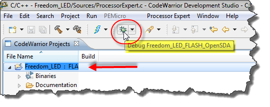
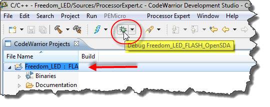
To download and debug, I press the debug toolbar icon. An annoying thing in Eclipse is I first need to *select* the project first to select the right debug configuration:
So I select the project, then hover over the icon to make sure my project is selected. Otherwise I use the small drop down of the debug toolbar icon to select the right configuration:
Starting Debugger
This will start the debugger, and I can use the toolbar items in the Debug view to step through my code:
debugging the application
Source Code
The project I have created in above steps can be downloaded from this link.
Summary
The steps presented here are really generic, and work for many boards and microcontrollers, especially for the Kinetis family. All what I need to know is the information to which pin the LED’s are connected. With this it is very easy to create a bare board (without RTOS) application blinking LED’s.


