


Table of Contents
This article offers a technical breakdown of Electronic Stability Control (ESC), a critical technology for preventing vehicle skids and improving driver safety. We will explore its core functions, system architecture, and the key electronic components that make it possible.
The Core Function of Electronic Stability Control (ESC)
Electronic Stability Control (ESC) is an active safety system engineered to enhance a vehicle's steering stability. Its primary function is to prevent wheel skid—where locked wheels slide across the road surface—and to help the driver maintain the intended path. By improving the vehicle's stability during cornering or on slippery surfaces like ice or wet pavement, ESC significantly reduces the risk of traffic accidents.
At its heart, ESC is an intelligent integration of three foundational technologies:
- Anti-lock Braking System (ABS): Prevents wheels from locking during hard braking.
- Traction Control System (TCS): Prevents wheel spin during acceleration.
- Yaw Control: Monitors the vehicle's rotation on its vertical axis to detect and counter oversteer or understeer.
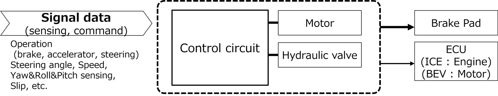
By combining vehicle stabilization, anti-slip, and brake-assist functions, ESC offers a comprehensive safety net. It processes data from various sensors and precisely controls the individual brakes on all four wheels, making meticulous adjustments to the vehicle's position. This capability is especially crucial for maintaining control in emergency evasive maneuvers or on treacherous road conditions.
(Fig. 1 Role of ESC)
Distinguishing ESC from ABS
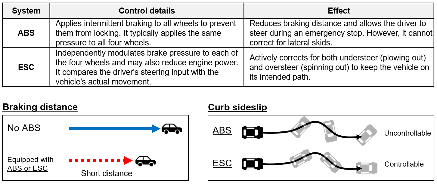
While often mentioned together, ESC and ABS have fundamentally different roles. The primary job of an Anti-lock Braking System (ABS) is to prevent the wheels from locking up when a driver brakes hard. This allows the driver to maintain steering control while braking and reduces the vehicle's skidding behavior, but it cannot control a vehicle's sideslip (lateral movement).
Electronic Stability Control, however, is designed specifically to prevent both slip and skids, giving the driver more complete authority over the vehicle's dynamics. Unlike ABS, ESC can actively manage sideslips, which is critical for maintaining stability through sharp curves or on uneven road surfaces.
(Fig. 2 Difference between ABS and ESC)
Market Dynamics and Engineering Demands
The adoption of ABS and ESC is widespread and expected to continue growing. This trend places new demands on the underlying technology. To enhance vehicle performance, brake control systems require higher accuracy. Concurrently, there is a strong push for miniaturization to improve fuel efficiency and system redundancy to guarantee safety.
From an electronic component standpoint, these demands create significant engineering challenges. The goals of "high accuracy," "miniaturization," and "redundancy" must be achieved while addressing issues like increased power loss (which generates heat), insufficient heat resistance, and overall power consumption.
A Look Inside: The Circuit Configuration of an ESC System
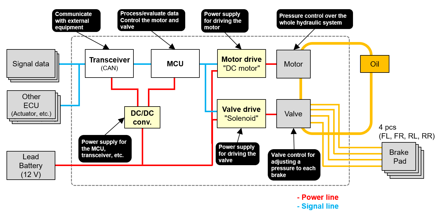
The ESC system is a complex network of electronic components working in unison. A typical configuration includes:
- Transceiver: A device or circuit that communicates with external equipment (through CAN).
- Microcomputer (MCU): Processes/evaluates data, and controls the motor and brake pressure valve.
- DC/DC converter: Supplies power to the MCU and transceiver.
- Motor drive circuit: A power supply for driving the motor.
- Valve drive circuit: A power supply for driving the brake pressure valve.
- Motor: Controls the pressure of the whole hydraulic system.
- Valve: Controls the pressure adjustment valve of each brake.
(Fig. 3 Overall configuration of the ESC)
A Breakdown of Individual Circuits and Key Components
1. Transceiver Circuit
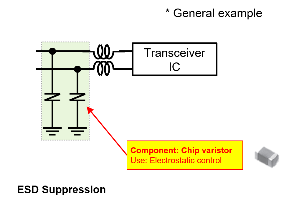
The transceiver facilitates communication over data lines (e.g., CAN, Ethernet). These lines are susceptible to external noise and electrostatic discharge (ESD), which can damage the transceiver IC. To mitigate this risk, chip varistors are commonly integrated as a protective measure against ESD events.
[Components used]
ESD noise elimination: Chip varistor
POINT- With a wide range of capacitance characteristics, the chip varistor suppresses electrostatic discharge (ESD) noise while keeping the communication quality of the circuit intact.
- With its capacitance ranging from 8 pF to 250 pF, the chip varistor operates effectively at low and high communication speeds.
(Fig.4 Components used in the tranceiver)
2. DC/DC Converter
This circuit, primarily composed of an FET, an inductor, and capacitors, is crucial for power regulation. Key components include:
Conductive Polymer Hybrid Aluminum Electrolytic Capacitors: Used for noise filtering at the input and smoothing the voltage at the output.
Automotive-Grade Power Inductor: Essential for the voltage conversion process.
High-Precision Chip Resistors: Used for accurate voltage monitoring and feedback.
[Components used]
Noise elimination, switching, and smoothing: Conductive polymer hybrid aluminum electrolytic capacitor
POINT- The capacitor offers high capacitance, low ESR, and high ripple-suppression performance, thus contributing to a reduction in the size of the circuit and an increase in the power capacity (low voltage and large current) of the circuit.
- Having capacitance characteristics that can cut off high-frequency components, the capacitor eliminates a wide range of high-frequency noises that are generated by a high-frequency switching of the circuit.
Voltage conversion: Power Inductors for Automotive application
POINT- Inductors made of a metallic magnetic material suffer less power loss and carry a large current, thus contributing to a reduction in the size of the circuit and an increase in the power capacity (low voltage and large current) of the circuit.
- Having loss characteristics in a higher frequency range (low ACR), the inductor contributes to the suppression of power loss caused by high-frequency switching of the circuit.
Voltage measurement: Chip resistor (high-precision chip resistor)
POINT- The chip resistor with a thin-film structure offers a small resistance tolerance and a low TCR, thus contributing to high-precision control of the output characteristics of the circuit.

(Fig. 5 Components used in the DC/DC converter)
3. Motor Drive Circuit
This circuit uses switching elements (FETs) to convert voltage and drive the motor. The high-frequency switching action is a significant source of electronic noise. To manage this:
A noise filter, consisting of an inductor and a capacitor, is placed at the input to handle voltage fluctuations.
Gate resistors are connected to the switching elements to suppress noise generated during on/off transitions.
[Components used]
Noise elimination and smoothing: Conductive polymer hybrid aluminum electrolytic capacitor
POINT- The capacitor offers high capacitance, low ESR, and high ripple-suppression performance, thus contributing to a reduction in the size of the circuit and an increase in the power capacity (low voltage and large current) of the circuit.
- Having capacitance characteristics that can cut off high-frequency components, the capacitor eliminates a wide range of high-frequency noises that are generated by a high-frequency switching of the circuit.
Noise elimination and smoothing: Power Inductors for Automotive application
POINT- Inductors made of a metallic magnetic material suffer less power loss and carry a large current, thus contributing to a reduction in the size of the circuit and an increase in the power capacity (low voltage and large current) of the circuit.
- Having loss characteristics in a higher frequency range (low ACR), the inductor contributes to the suppression of power loss caused by high-frequency switching of the circuit.
Suppressing gate-driven noise from the switching elements: Chip resistor (small and high-power chip resistor)
POINT- With its original resistance pattern, electrode structure, etc., the chip resistor is small in size and yet handles high-power operations, thus contributing to a reduction in the size of the circuit.
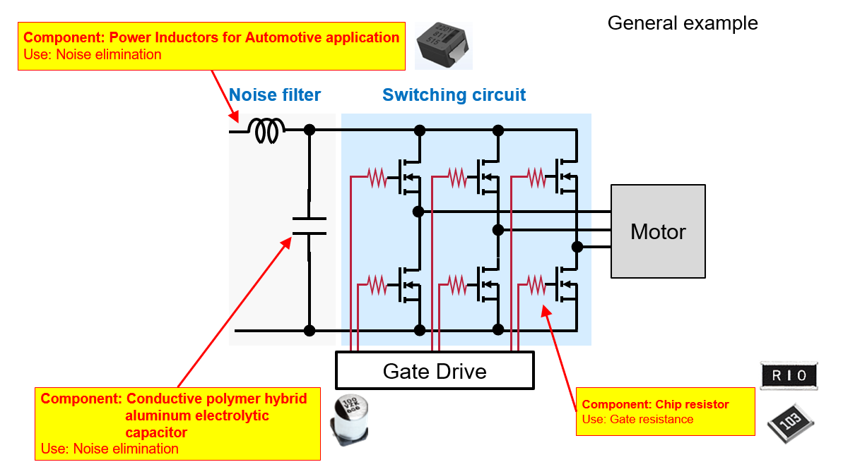
(Fig. 6 Components used in the motor drive circuit)
4. Valve Drive Circuit
The valve drive circuit controls the solenoid that actuates each brake valve. It consists of the solenoid itself, an FET for on/off control, and a diode to protect against voltage surges from the solenoid coil. Similar to the motor drive circuit, a gate resistor is used on the FET to suppress switching noise and ensure clean operation.
[Components used]
Suppressing gate-driven noise from the switching elements: Chip resistor (small and high-power chip resistor)
POINT- With its original resistance pattern, electrode structure, etc., the chip resistor is small in size and yet handles high-power operations, thus contributing to a reduction in the size of the circuit.
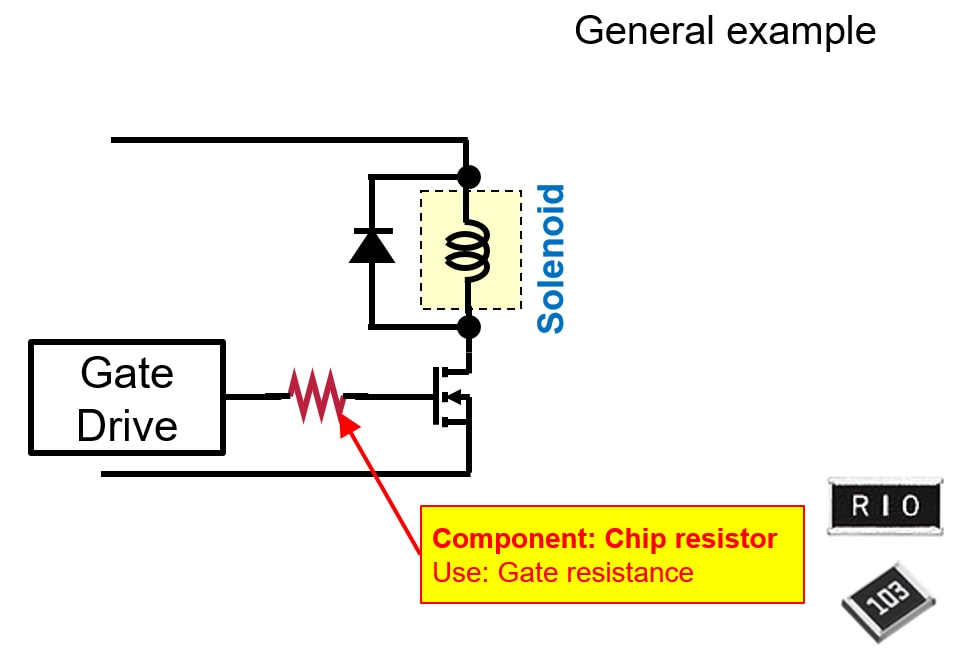
(Fig. 7 Components used in the valve drive circuit)
Conclusion
Electronic Stability Control is a sophisticated safety technology that integrates ABS, TCS, and yaw control to stabilize a vehicle, prevent skids, and support the driver in critical situations. As ESC systems become standard, the demand for higher precision, smaller and lighter components, and greater system redundancy will continue to drive innovation in automotive electronics. Engineers are tasked with overcoming challenges related to power efficiency and thermal management to develop the next generation of these life-saving systems.
| Component | Feature | Low loss | Small size | High resistance to heat |
| Conductive polymer hybrid aluminum electrolytic capacitor |
Low ESR High reliability |
 |
|
|
| Power Inductors for Automotive application | Large current, low loss High reliability |
|
|
|
| High precision, high resistance to heat | |
|
||
| Chip varistor | Small and light | |