


As the automotive industry accelerates toward higher‑level autonomous driving, the Domain Control Unit (DCU) has become a central element of next‑generation vehicle architecture. DCUs consolidate data from multiple sensors, make real‑time decisions, and coordinate critical control functions—requiring components that deliver high current capability, low loss, miniaturization, and excellent EMC robustness.
This technical guide provides an engineer‑friendly explanation of DCU roles, system configurations, and design challenges—and showcases how Panasonic Industry components support reliable, high‑performance DCU development.
If you're designing automotive ECUs, power modules, or sensing interfaces, this guide will help you choose optimal Panasonic devices for your next project.
If you're designing automotive ECUs, power modules, or sensing interfaces, this guide will help you choose optimal Panasonic devices for your next project.
1. ADAS vs. AD: Why DCUs Are Increasing Rapidly
Advanced Driver Assistance Systems (ADAS) support the human driver, while Autonomous Driving (AD) shifts responsibility to the vehicle itself. According to SAE levels:
- Level 0–2: Human‑driven with partial assistance
- Level 3–5: Vehicle executes most or all driving tasks
As vehicles progress into Level 3 and beyond, the sensor count and data throughput grow dramatically. This makes centralized processing, fast communication, and robust power management more critical—hence the rapid adoption of DCUs.
| Level | Name | Driven by | Driving area | Remarks |
|---|---|---|---|---|
| 0 | No driving automation | Human driver | - | The human performs all driving tasks |
| 1 | Driving assistance | Human driver | Limited | Provides driving assistance in part through tasks such as monitoring the vehicle's perimeter |
| 2 | Partial driving automation | Human driver | Limited | "Hands off" - Automates driving under specific conditions |
| 3 | Conditional driving automation | Vehicle | Limited | "Eyes off" - Automates driving under specific conditions |
| 4 | Advanced driving automation | Vehicle | Limited | "Brain off" - Automates driving under specific conditions |
| 5 | Full driving automation | Vehicle | No limitations | The vehicle performs all driving tasks under all conditions |
Table 1 Definition of autonomous driving by level
2. Core System Blocks Required for ADAS / AD
A complete sensing‑to‑control chain typically includes:
Sensor ECU
Cameras, RADAR, LiDAR, and ultrasonic sensors gather environmental data.
Main ECU / DCU
Performs high‑speed data fusion, perception, and decision‑making.
Actuator ECU
Controls braking, steering, powertrain, and other vehicle dynamics.
A DCU sits at the heart of this system, enabling seamless communication between domains and ensuring reliable autonomous operation.
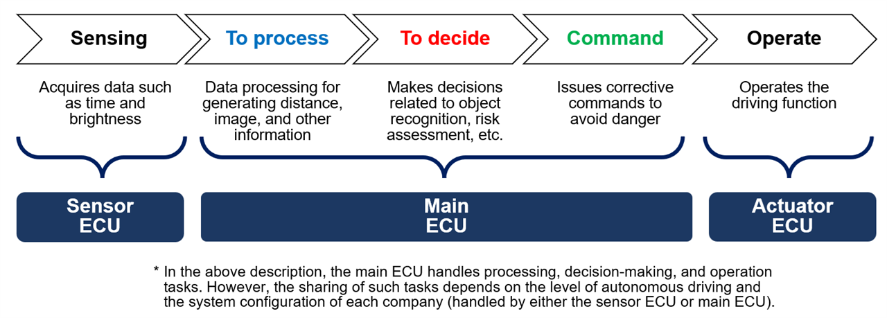
Figure 1 Overall system flow (from sensing to operation)
3. Domain vs. Zone Architecture—Where DCUs Fit
As OEMs evolve their E/E architectures, two major approaches are used:
Domain Type (Distributed)
- Each function (ADAS/AD, powertrain, body, cockpit, etc.) has its own DCU
- Processing is performed inside each domain
- Domains communicate via gateway ECUs
Ideal for: Level 2 and Level 2+ applications
Zone Type (Centralized)
- ECUs grouped by vehicle location (front, rear, cabin)
- A central computer consolidates all zone‑level inputs
- Supports massive data throughput and high compute requirements
Ideal for: Level 3–5 and next‑generation EV platforms
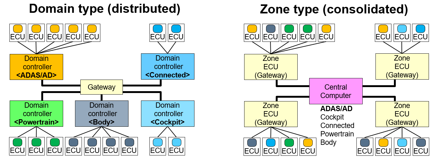
| Configuration | Connection | Network |
|---|---|---|
| Domain type | Consolidates domain-specific ECUs for each category (domain) All domains are connected via the Gateway Data processing is performed in each domain-specific ECU |
Common network standards are used for communication between sensors and domains Common network standards are used for communication between the domains and Gateway |
| Zone type | Consolidates ECUs of different categories in each zone such as the front and rear of the vehicle Consolidates data from each zone to the Central Computer Integrates and concentrates data processing in the Central Computer |
There is a mixture of different network standards for communication between sensors and zones Common network standards are used for communication between the zones and Central Computer |
4. What Exactly Does a DCU Do?
A DCU integrates multiple functions:
- High‑speed communication with sensors and other ECUs
- Data fusion and environment recognition using SoCs and dedicated processors
- Memory management (Flash, DDR) for algorithms and sensor data
- Power management through multiple isolated DC/DC converters
- Command execution to actuators and cooperating domains
This makes DCUs one of the most component‑dense areas in modern automotive electronics.
5. Component Requirements for High‑Performance DCUs
DCUs demand components with:
- High current tolerance for heavy processing loads
- Low loss to minimize thermal buildup
- High‑frequency capability for switching and communication
- Miniaturization for dense board layouts
- Highly stable voltage characteristics
Panasonic Industry specifically develops components aimed at fulfilling these stringent requirements.
6. Inside the DCU: Key Circuits and Recommended Components
6‑1: High‑Speed Transceiver Interfaces (CAN, Ethernet, LVDS)
During communication, DCUs are exposed to ESD surges and noise. To protect transceiver ICs and maintain signal quality, Panasonic offers:
① Chip Varistors
- Wide capacitance range (8–250 pF)
- Ideal for low‑ to mid‑speed communication lines
② ESD Suppressors
- Ultra‑low capacitance (0.1 pF)
- Perfect for high‑speed interfaces such as automotive Ethernet
 Explore products:
- Chip Varistor: Farnell® UK
- ESD Suppressor: Farnell® UK
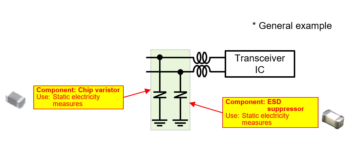
Figure 4 Components used in a transceiver IF
6‑2: Power Delivery—DC/DC Converter Architectures
DCUs require multiple supply rails to power SoCs, memory, MCUs, and transceivers. Panasonic components are essential for each converter block.
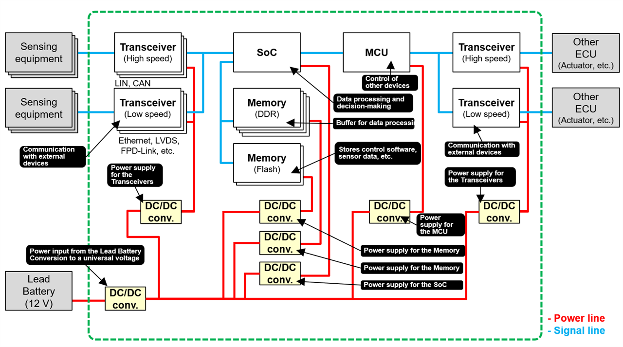
Figure 3 DCU system configuration
Three DC/DC Converter Types
| Type | Typical Use | Characteristics |
|---|---|---|
| A (Multiphase) | SoCs / FPGAs | Very high current, polymer capacitors + MLCCs |
| B | DDR memory | High ripple current, large‑capacitance smoothing |
| C | General rails | Standard DC/DC topology |
Key Panasonic Components for DC/DC Converters
① Conductive Polymer Hybrid Aluminum Electrolytic Capacitors
- High capacitance, low ESR
- Excellent high‑frequency performance for noise suppression
- Supports miniaturization and high‑current operation
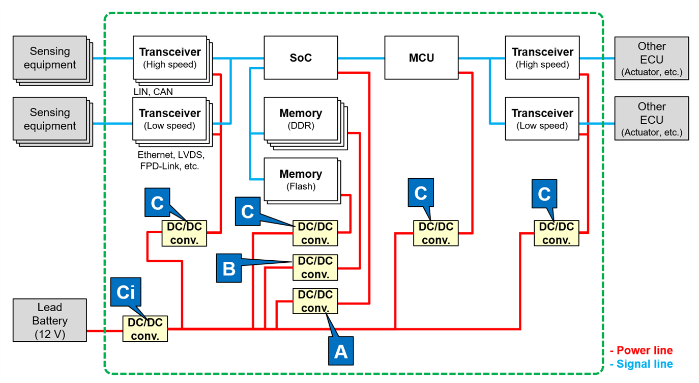
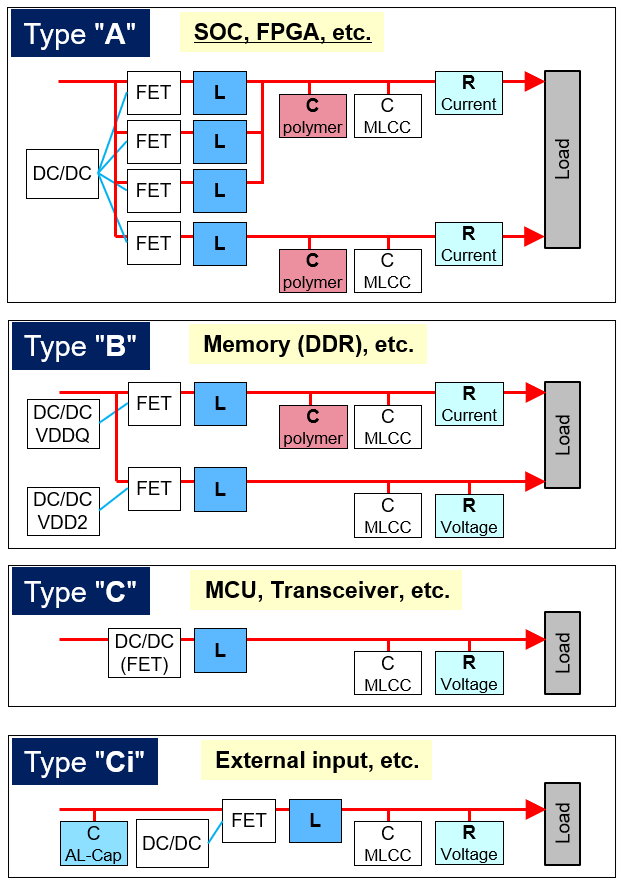
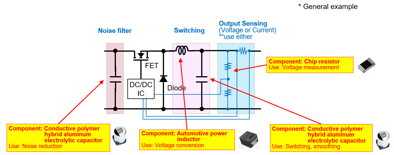
Figure 6 Components used in a DC/DC converter
② Automotive Power Inductors
- Low loss thanks to metallic magnetic materials
- High current capability
- Optimized for high‑frequency switching
③ High‑Precision Chip Resistors
- Low TCR and low resistance tolerance
- Suitable for voltage sensing feedback loops in converters
7. Summary: Panasonic Components Accelerate DCU Innovation
As autonomous driving advances, DCUs must handle increasing data loads, higher currents, and tighter power requirements. Panasonic Industry provides an extensive lineup of components engineered specifically for these challenges:
| Component Type | Key Features |
|---|---|
| Conductive Polymer Hybrid Capacitors | Low ESR, high ripple tolerance |
| Automotive Power Inductors | High current, low loss |
| High‑Precision Chip Resistors | High accuracy, high thermal reliability |
| Chip Varistors | ESD protection for various communication speeds |
| ESD Suppressors | Ultra‑low capacitance for high‑speed lines |
These components support miniaturization, efficiency, reliability, and high‑speed performance—all essential for next‑generation DCU design.
Ready to Start Your DCU Design?
If you're developing automotive ECUs, ADAS platforms, or central computing modules, explore Panasonic components on Farnell:
- Panasonic's advanced passive components can help you enhance reliability, reduce board size, and meet the strict demands of modern autonomous driving systems.