


A Practical Guide to Panasonic Industry Chip Resistors
As electronic devices continue to shrink while delivering ever-greater performance, thermal design has become one of the most critical—and often underestimated—challenges in circuit development. Highly integrated ICs and densely packed surface‑mount components generate more heat than ever before, placing new demands on designers tasked with ensuring long‑term reliability.
To address these challenges, Panasonic Industry promotes a design approach that is rapidly becoming essential in advanced PCB development: terminal‑temperature‑based power rating. This technique provides far more accurate guidance than traditional ambient‑temperature‑based ratings—especially for today’s compact SMD resistors.
In this article, we explain why terminal temperature matters, how to measure it correctly, how international standards (including JEITA) are evolving, and how Panasonic’s chip resistors can help ensure reliable, thermally sound circuit performance.
1. From Leaded Components to SMD: Why Thermal Behavior Has Changed
Historically, through‑hole (leaded) resistors dissipated most of their heat—up to 90%—directly into the surrounding air. Their rated power was therefore determined with ambient temperature as the reference point.
Today’s electronics, however, rely heavily on surface‑mount resistors, which behave very differently:
Leaded Resistors
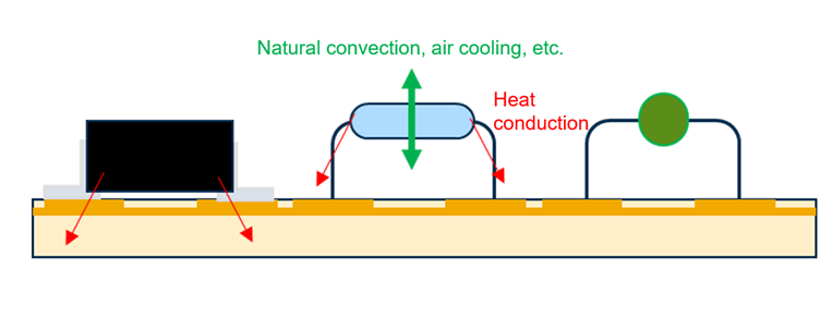
- Large surface area → excellent heat dissipation through convection and radiation
- Minimal heat transfer to the PCB
- Ambient temperature is the dominant variable
Heat effect image of resistor with leads
- With thin and long lead terminals, the component conducts (releases) a small amount of heat to the mounting board.
- The large surface area of the component allows for great convection, radiation, and dissipation of heat.
Surface‑Mount Chip Resistors
- Very small surface area → limited convection and radiation
- Large solder‑pad contact area → significant heat conduction into the PCB
- Strongly affected by neighboring components’ heat
Because SMD resistors experience heat not only from their own power dissipation but also from the board, relying solely on ambient temperature can lead to significant errors in power‑rating calculations.

Heat effect image of surface-mounted component
- Having connection terminals with a large contact area, the component conducts (releases) a large amount of heat to the mounting board.
- The small surface area of the component lessens the ability of convection, radiation, and dissipation of heat.
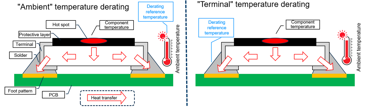
2. Why Terminal‑Temperature‑Based Specification Is Becoming Essential
To solve this mismatch, manufacturers—including Panasonic Industry—have adopted a more precise method: measuring power rating based on terminal temperature rather than ambient air temperature.
This approach allows engineers to:
- Quantify the exact thermal load applied to a resistor during operation
- Reduce design uncertainty caused by complex heat flow within a dense PCB
- Improve prediction accuracy for component lifetime and failure risk
The trend has grown strong enough that industry organizations such as JEITA have begun issuing study reports and guidance documents, including RCR‑2114: Study for the derating curve of fixed surface‑mount resistors, which Panasonic follows when defining its product specifications.
3. Measuring Terminal Temperature: Methods and Key Considerations
Terminal temperature can be measured using two common tools:
| Method | Advantages | Limitations |
|---|---|---|
| Thermocouple | High accuracy, direct measurement | Requires physical contact; heat conduction through wires may distort readings |
| Infrared thermography | Contactless, easy to use, wide temperature range | Cannot measure through glass; requires high surface emissivity (may need black coating) |
Because many practical evaluations occur at the prototype stage and involve very small components, thermocouples are the most commonly used tool.
3.1 Choosing the Right Thermocouple
Thermocouples vary in heat conductivity and measurement characteristics:
-
K‑type
Ideal for chip resistors due to low heat conductivity and minimal thermal interference. -
T‑type
Highly accurate but conducts heat more easily, which can artificially lower the reading on small components.
For reliable results, selecting a thermocouple with thin wires and low thermal mass is essential.
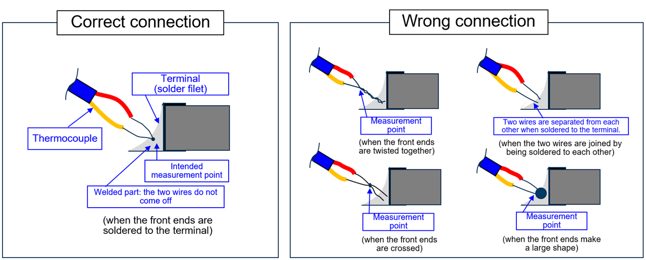
3.2 How to Prepare and Attach a Thermocouple Correctly
To ensure accurate readings:
-
Properly weld the wire tips
- Twisting or soldering the wires together is not enough
- Use spot‑welding to form a small, stable junction
-
Avoid oversized or crossed wire tips
- An oversized joint or a stray wire can act as a heat sink
- This causes temperature readings to fluctuate or drop artificially
-
Attach precisely to the center of the solder fillet
- Placing the junction near the edge or outside of the fillet compromises accuracy
- The thermocouple must be exactly at the intended thermal reference point
Panasonic’s evaluation examples emphasize correct positioning, as shown in their measurement diagrams.
3.3 Sources of Measurement Error
Even when the thermocouple is attached correctly, two main factors may introduce errors:
- Lot‑to‑lot inconsistency in the thermocouple’s electromotive characteristics
- Voltage measurement error in the data logger (channel‑to‑channel variation)
Engineers should always account for these factors when interpreting measurement results.
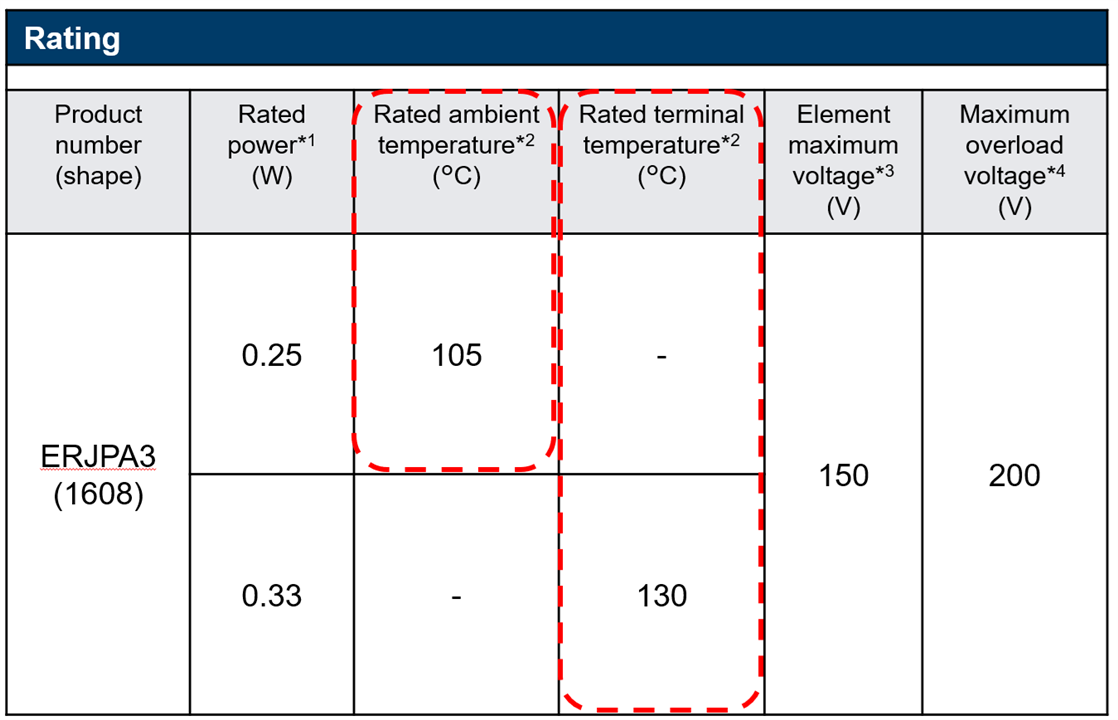
4. Selecting Components Based on Terminal‑Temperature Rating
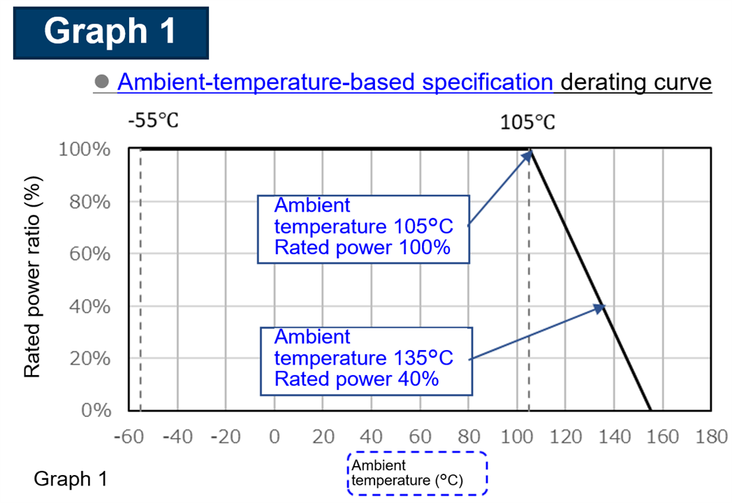
Panasonic Industry provides both ambient‑temperature‑based and terminal‑temperature‑based ratings in many resistor datasheets. A sample from the ERJPA3 (0603) series illustrates how both specifications coexist:
Ambient‑Temperature‑Based Derating Example
- 105 °C → 100% rated power
- 135 °C → 40% rated power
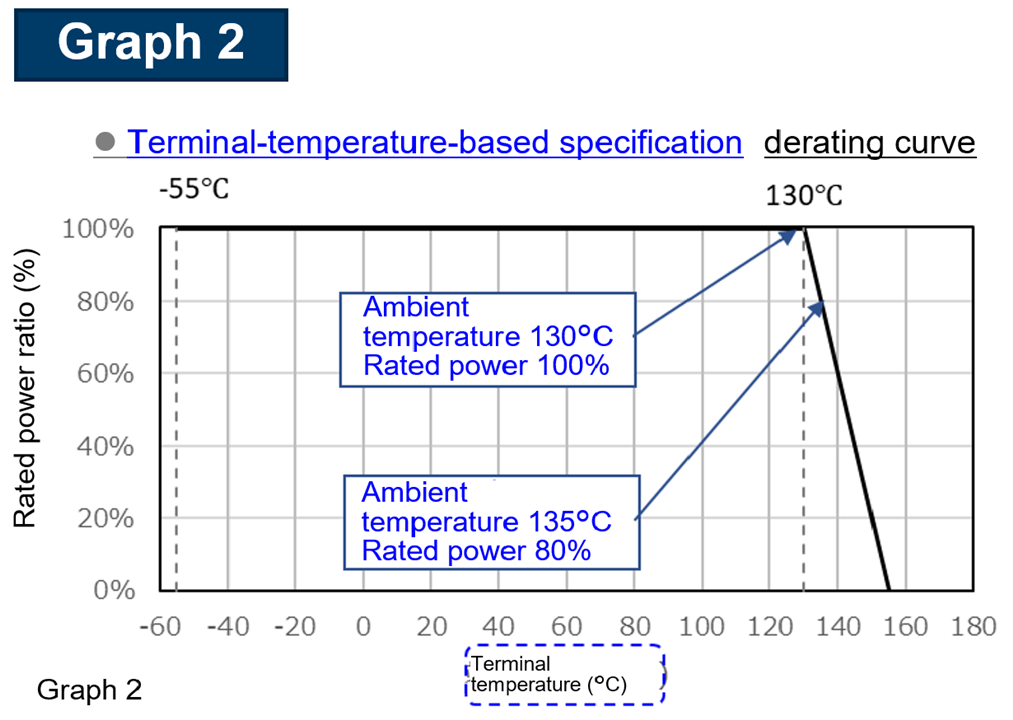
Terminal‑Temperature‑Based Derating Example
- 130 °C → 100% rated power
- 135 °C → 80% rated power
In cases where both ratings are listed and the design environment is complex (high density, high heat flow), Panasonic recommends prioritizing the terminal‑temperature‑based rating for greater design accuracy.
5. Why This Matters for Today’s Designers
As electronics continue to evolve toward higher power density and smaller footprints, thermal reliability becomes a determining factor in product lifespan and performance. Terminal temperature offers a more reliable metric than ambient conditions, especially for SMD resistors mounted on densely populated PCBs.
Key takeaways:
- SMD resistors experience significantly more board‑influenced heating than leaded components
- Terminal‑temperature‑based rating produces more accurate real‑world load calculations
- Using the correct thermocouple and attachment technique is critical to obtaining reliable data
- Panasonic Industry provides clear, JEITA‑aligned specifications to support accurate thermal design
Explore Panasonic Chip Resistors on Farnell
Panasonic Industry offers a broad lineup of high‑reliability chip resistors engineered for stable performance under demanding thermal conditions.
 Browse Panasonic chip resistors on Element14
- ERJ‑P Series – High‑power, high‑reliability thick‑film resistors
- ERJ‑H Series – High‑precision, low‑TC components for tight‑tolerance design
By integrating terminal‑temperature‑based evaluation into your workflow, you’ll achieve more robust circuit designs—and selecting Panasonic’s thermally optimized resistors will help ensure your products perform reliably in even the most demanding applications.