element14 Community
element14 Community
    Register Log In
  • Site
  • Search
  • Log In Register
  • Community Hub
    Community Hub
    • What's New on element14
    • Feedback and Support
    • Benefits of Membership
    • Personal Blogs
    • Members Area
    • Achievement Levels
  • Learn
    Learn
    • Ask an Expert
    • eBooks
    • element14 presents
    • Learning Center
    • Tech Spotlight
    • STEM Academy
    • Webinars, Training and Events
    • Learning Groups
  • Technologies
    Technologies
    • 3D Printing
    • FPGA
    • Industrial Automation
    • Internet of Things
    • Power & Energy
    • Sensors
    • Technology Groups
  • Challenges & Projects
    Challenges & Projects
    • Design Challenges
    • element14 presents Projects
    • Project14
    • Arduino Projects
    • Raspberry Pi Projects
    • Project Groups
  • Products
    Products
    • Arduino
    • Avnet Boards Community
    • Dev Tools
    • Manufacturers
    • Multicomp Pro
    • Product Groups
    • Raspberry Pi
    • RoadTests & Reviews
  • Store
    Store
    • Visit Your Store
    • Choose another store...
      • Europe
      •  Austria (German)
      •  Belgium (Dutch, French)
      •  Bulgaria (Bulgarian)
      •  Czech Republic (Czech)
      •  Denmark (Danish)
      •  Estonia (Estonian)
      •  Finland (Finnish)
      •  France (French)
      •  Germany (German)
      •  Hungary (Hungarian)
      •  Ireland
      •  Israel
      •  Italy (Italian)
      •  Latvia (Latvian)
      •  
      •  Lithuania (Lithuanian)
      •  Netherlands (Dutch)
      •  Norway (Norwegian)
      •  Poland (Polish)
      •  Portugal (Portuguese)
      •  Romania (Romanian)
      •  Russia (Russian)
      •  Slovakia (Slovak)
      •  Slovenia (Slovenian)
      •  Spain (Spanish)
      •  Sweden (Swedish)
      •  Switzerland(German, French)
      •  Turkey (Turkish)
      •  United Kingdom
      • Asia Pacific
      •  Australia
      •  China
      •  Hong Kong
      •  India
      •  Korea (Korean)
      •  Malaysia
      •  New Zealand
      •  Philippines
      •  Singapore
      •  Taiwan
      •  Thailand (Thai)
      • Americas
      •  Brazil (Portuguese)
      •  Canada
      •  Mexico (Spanish)
      •  United States
      Can't find the country/region you're looking for? Visit our export site or find a local distributor.
  • Translate
  • Profile
  • Settings
PCB Design, Prototyping and Production
  • Products
  • More
PCB Design, Prototyping and Production
PCB Forum SiC403 overheating with empty load
  • Blog
  • Forum
  • Documents
  • Leaderboard
  • Files
  • Members
  • Mentions
  • Sub-Groups
  • Tags
  • More
  • Cancel
  • New
Join PCB Design, Prototyping and Production to participate - click to join for free!
Actions
  • Share
  • More
  • Cancel
Forum Thread Details
  • State Verified Answer
  • Replies 8 replies
  • Subscribers 118 subscribers
  • Views 2137 views
  • Users 0 members are here
  • buck
  • dc-dc
  • regulators
  • Design
  • synchronous
  • sic
Related

SiC403 overheating with empty load

Kaizen
Kaizen over 3 years ago

Hello, 

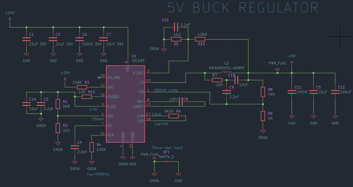
I'm currently designing a very compact board that should take a 24V power source and regulate it down to 5V (up to 4A) to power RGB led strips. The board has some specific mechanical constraints because it would need to slide inside aluminum profiles and solder directly over the strip. 

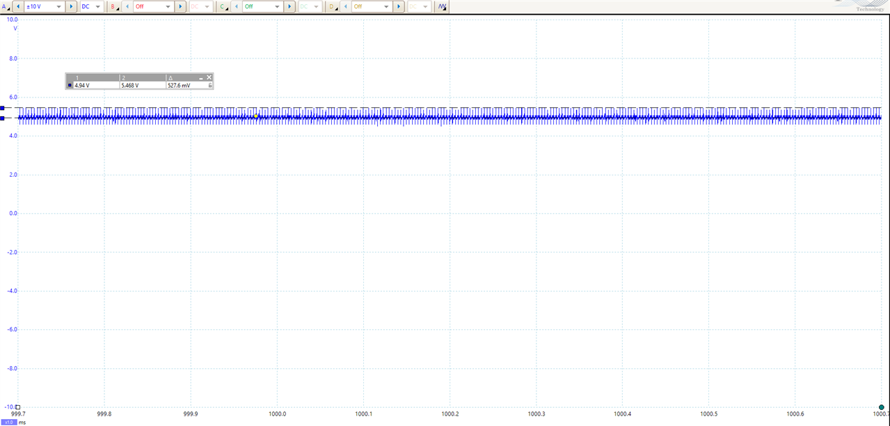
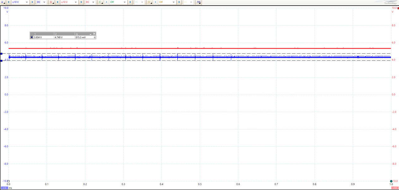
I ran simulations on Vishay transim's website and for 5V 4A the chip should not go over 40C, but when I tested my board I saw the LDO is consuming around 1W and is overheating the chip until a point where it either goes to overtemperature protection or the chip just dies. I got another board consuming up to 150mA when ran at 15V.

Is there something wrong with my schematic? I thank maybe as I'm using it to output 5V I should put a resistor divider to V_out but it changed nothing. I checked my schematic against their datasheet, the eval board and the transim example but none of them are similar to each other so I don't know which one is the working one.

I already tried shutting down the regulator output to keep the LDO and the consumption is the same, which is why I think this is the LDO. I also checked the 5V output and the output seems nice but the power good pin is always at low state (I patched a pull-up resistor between pgood and vdd to check that).

Do you have ideas of things I could do to diagnose this issue?

Thanks,

image

  • Sign in to reply
  • Cancel

Top Replies

  • Kaizen
    Kaizen over 3 years ago in reply to michaelkellett +4 verified
    Hi! Big news, it finally worked! I post what I did here in case it could help someone :) I have made a few big changes though: - The output voltage have been adjusted to 5.09V (instead of 5.6V), which…
  • michaelkellett
    michaelkellett over 3 years ago +1
    What do you see on pin 3, VDD (AC and DC) What sort of capacitors are you using. What current do you see on the input with the LDO disabled/enabled at different input voltages. MK
  • michaelkellett
    michaelkellett over 3 years ago in reply to Kaizen +1
    Just a thought here, in the data sheet they have 2 x 4.7uF on pin 3, You have a nominal 2.2uF. The VDD signal should not be so noisy. Try using resistor and capacitor values closer to the data sheet…
  • michaelkellett
    0 michaelkellett over 3 years ago

    What do you see on pin 3, VDD (AC and DC)

    What sort of capacitors are you using.

    What current do you see on the input with the LDO disabled/enabled at different input voltages.

    MK

    • Cancel
    • Vote Up +1 Vote Down
    • Sign in to reply
    • Verify Answer
    • Cancel
  • Kaizen
    0 Kaizen over 3 years ago in reply to michaelkellett

    VDD is 4.94V, ripples of +-500mV total. This is all ceramic capacitor (X5R/X7R). In terms of currents, if I disable the chip (with ENL pin) it goes to 0mA.

    image

    When I use an external LDO it regulates very nicely and draws around 20mA at 4.5V (I tried with a 3.3v LDO I had but the voltage drop of my amp meter is too high so it does not give accurate data). On the second snapshot, blue is VDD and red is the regulator output. The chip stays at room temperature.

    image

    • Cancel
    • Vote Up 0 Vote Down
    • Sign in to reply
    • Verify Answer
    • Cancel
  • michaelkellett
    0 michaelkellett over 3 years ago in reply to Kaizen

    Just a thought here, in the data sheet they have 2 x 4.7uF on pin 3, You have a nominal 2.2uF.

    The VDD signal should not be so noisy.

    Try using resistor and capacitor values closer to the data sheet suggestion for R1, R2 and C2.

    For future reference when taking picturesof Picoscope output, try zooming in  more and using cursors to show time interval as well as voltage, turn on the settings pane as well so the samplig rate and filter settings show. Doing these things will make it much easier to understand the print outs.

    MK

    • Cancel
    • Vote Up +1 Vote Down
    • Sign in to reply
    • Verify Answer
    • Cancel
  • Kaizen
    0 Kaizen over 3 years ago in reply to michaelkellett

    I just added a 10uF capacitor to make sure this was enough (they recommend >10uF capacitance for <4.5V on the LDO), it seems to be working better indeed: at 10V input it uses ~35-40mA and starts switching to Vout. For R1 and R2 I lowered them but I cannot find the datasheet suggestion, I originally used the values from p23 of https://www.vishay.com/docs/62768/sic403abcd.pdf. Now they're 1K2/6K8.

    Now that it is using the switchover the LDO should be turning off. When I probe Vout it is very unstable because of the resistor divider I had to put from the output to Vout to lower the value from 5.4V to 5V. I'm currently using a divider of 1k2/15k (the datasheet gives this example for the values to use: `if an output voltage of VOUT = 8.5 V is required, setting R2 = 10 k and VOUT_PIN = 4.5 V results in R1 = 8870R`).

    I don't understand why the datasheet would want to power the chip through a voltage divider, that seems heavily unstable and now it is cycling between LDO output and the buck output for VDD. Do you think lowering the values to get <100R resistor between the output and Vout would be enough?

    Thanks for the tips for Picoscope, I almost never use the software so I'm still learning about the settings. I'll do that now :) 

    • Cancel
    • Vote Up 0 Vote Down
    • Sign in to reply
    • Verify Answer
    • Cancel
  • Kaizen
    0 Kaizen over 3 years ago in reply to Kaizen

    Some updates: I switched to a 100R/1K2 resistor divider between the output and Vout and added a 2.2uF capacitor on Vout too. Now the ripple issues I had on Vout disappeared but the LDO does not seems to turn off (assumption based on the current consumption) even though PGOOD is going high and VDD is exactly the same as Vout. It is currently powered at 10V and consumming ~50mA, so the issue is still there :(  I tried with various input voltages, the current increases when input voltage increases.

    The patched board now looks like this

    image

    • Cancel
    • Vote Up +1 Vote Down
    • Sign in to reply
    • Verify Answer
    • Cancel
  • michaelkellett
    0 michaelkellett over 3 years ago in reply to Kaizen

    Check out page 15 on the data sheet.

    There are some important design rules that must be followed
    to prevent forward bias of these diodes. The following two
    conditions need to be satisfied in order for the parasitic
    diodes to stay off.
    • VDD  VLDO
    • VDD  VOUT
    If either VLDO or VOUT is higher than VDD, then the respective
    diode will turn on and the SiC403 operating current will flow
    through this diode. This has the potential of damaging the
    device.

    Not sure if this is relevant but no time to look any more  - have to go home !

    MK

    • Cancel
    • Vote Up +1 Vote Down
    • Sign in to reply
    • Verify Answer
    • Cancel
  • Kaizen
    +1 Kaizen over 3 years ago in reply to michaelkellett

    Hi!

    Big news, it finally worked! I post what I did here in case it could help someone :)

    I have made a few big changes though:
    - The output voltage have been adjusted to 5.09V (instead of 5.6V), which allows me to remove the resistor divider to Vout
    - The EN/PSV is now pulled high to get into power save mode

    The first change have been made because I noticed that even after lowering the resistor value and adding a capacitor on Vout, the LDO was still running. In fact on startup I noticed that the chip tried to switch and the voltage dropped (so the switchover went back to LDO), but it never retried after that. I don't know why because the voltage was almost the same as VLDO... After this patch I went from 50-60mA current consumption to ~35mA. Luckily the chip went warm but not super-hot and kept this consumption even when during load-testing (up to 2A output current)

    The second change have been made to lower the empty load current consumption, which dropped it from 35mA to 9mA!

    So now it's working well, thank you so much for your help!

    • Cancel
    • Vote Up +4 Vote Down
    • Sign in to reply
    • Verify Answer
    • Reject Answer
    • Cancel
  • michaelkellett
    0 michaelkellett over 3 years ago in reply to Kaizen

    Happy to hear it's working for you now !

    MK

    • Cancel
    • Vote Up 0 Vote Down
    • Sign in to reply
    • Verify Answer
    • Cancel
element14 Community

element14 is the first online community specifically for engineers. Connect with your peers and get expert answers to your questions.

  • Members
  • Learn
  • Technologies
  • Challenges & Projects
  • Products
  • Store
  • About Us
  • Feedback & Support
  • FAQs
  • Terms of Use
  • Privacy Policy
  • Legal and Copyright Notices
  • Sitemap
  • Cookies

An Avnet Company © 2025 Premier Farnell Limited. All Rights Reserved.

Premier Farnell Ltd, registered in England and Wales (no 00876412), registered office: Farnell House, Forge Lane, Leeds LS12 2NE.

ICP 备案号 10220084.

Follow element14

  • X
  • Facebook
  • linkedin
  • YouTube