I've been a member for a long time, but this is my first time posting.
I guess it's a bit too late for a presentation, but I'm a software engineer with a fascination for electronics; It's been my hobby for more than 20 years, and I keep learning new things almost every day.
I recently became interested in frequency domain analysis. I know it has countless applications in the Ham/radio world, but I was thinking about more general-purpose use cases; like identifying cross-talk or interference on a PCB design.
I know that's a huge topic and there's some well known general advice and practices to reduce this, like ground planes and decoupling capacitors, and filters... but I wanted to check how bad it could be, if absolutely no sane advice or practice was followed.
So I came up with this ugly PCB as my ultimate test-bed:

This is honestly not far from a PCB I would have designed when I was starting in electronics. I liked having nothing but the tracks on the board.
For a first test, I injected two signals from a signal generator on the left side of the PCB, both very stable and clean. One of them a 7 Mhz sine wave, and the other one a 10 Mhz square wave. I picked two relatively close frequencies to see how easy (or hard) was going to be telling them apart later.
Both traces start very far from each other on the left side of the PCB on big pads, and then they get closer together near the center, just to take on their own separate paths again as their approach the right side.
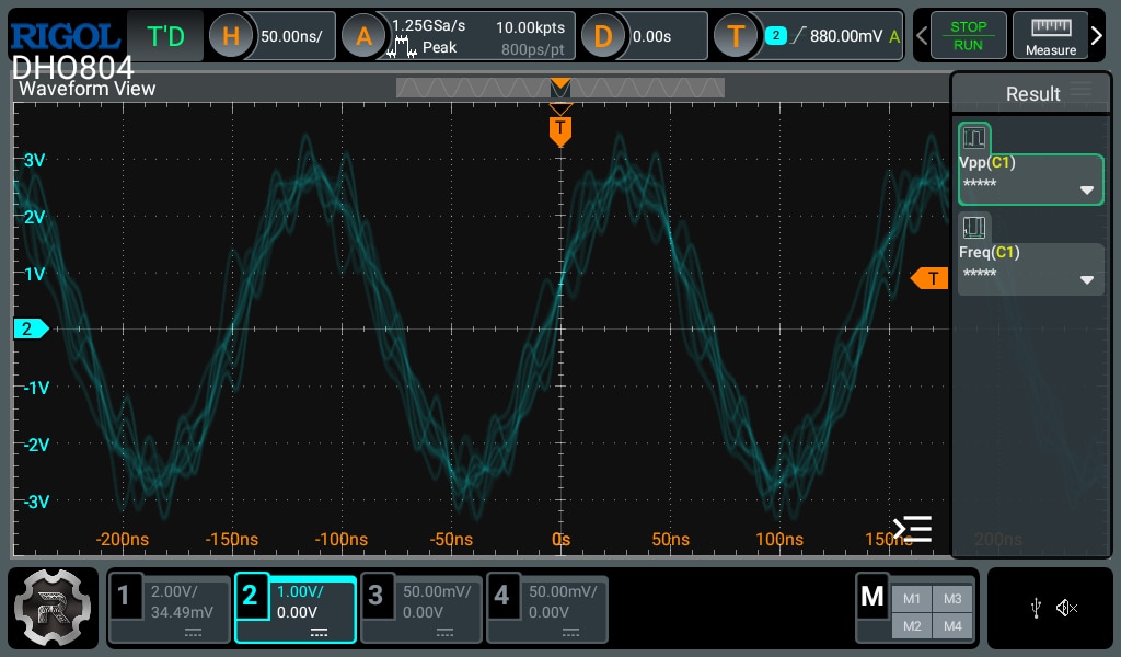
I'm monitoring the "output pad" on the right side for both waveforms on an oscilloscope, and while I was initially watching both on the screen of the scope, the one that I think looked more interesting was the output of the "sine wave" trace:

That's one messed up sine wave. For the record; without the square wave signal connected (or with the signal turned off), that wobbly sine-wave becomes a very clean, proper sinusoidal wave, so this was clearly the influence of the other signal.
I'm sure it's possible to use the FFT on the scope to dissect the frequency content of that signal,but I wanted to explore none-invasive methods. Something that I could use for a quick inspection and that didn't require probing around test points or component pins. Something that could potentially identify higher-frequency content outside of the range of my scope. And for that I went for a cheap "near field" probe, connected to a TinySA Ultra Spectrum Analyzer. You can actually see the near field "probe" hovering over the tracks in the first picture.
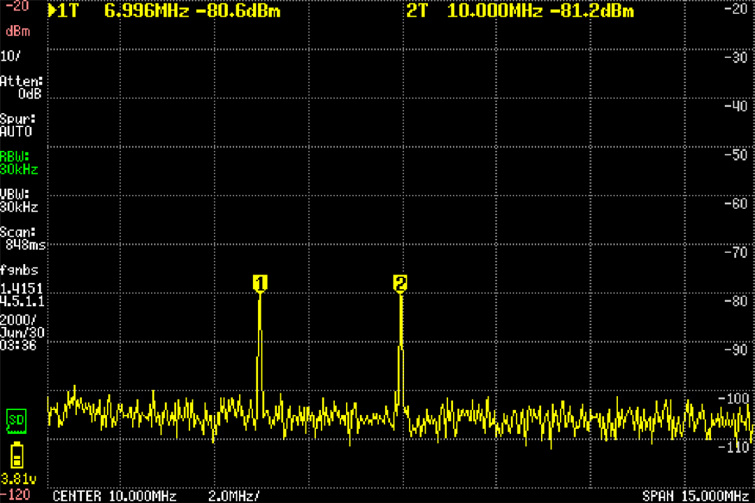
This is a capture from the TinySA:

I was honestly amazed at how well this worked. The probe captured perfectly the two main components of the coupled signal (both a 7 and a 10 Mhz component) even without touching the PCB. Because I zoomed tightly on the frequency range of both signals there's no harmonics from the square wave in sight.
The results were pretty exciting to me, but this left me curious about a couple of things. And I thought this forum was the perfect place to ask::
How often is this kind of debugging needed in real life? How frequently is this kind of analysis required? (other than when performing EMI emissions testing). Is there an area in electronics where cross-talk issues are more of a problem than in others? (for example is this problem worse in high-frequency applications?)
If any of you have an anecdote or story where cross-talk has been an issue, a mystery, or a lesson well learned, I'd love to hear it!
