element14 Community
element14 Community
    Register Log In
  • Site
  • Search
  • Log In Register
  • Community Hub
    Community Hub
    • What's New on element14
    • Feedback and Support
    • Benefits of Membership
    • Personal Blogs
    • Members Area
    • Achievement Levels
  • Learn
    Learn
    • Ask an Expert
    • eBooks
    • element14 presents
    • Learning Center
    • Tech Spotlight
    • STEM Academy
    • Webinars, Training and Events
    • Learning Groups
  • Technologies
    Technologies
    • 3D Printing
    • FPGA
    • Industrial Automation
    • Internet of Things
    • Power & Energy
    • Sensors
    • Technology Groups
  • Challenges & Projects
    Challenges & Projects
    • Design Challenges
    • element14 presents Projects
    • Project14
    • Arduino Projects
    • Raspberry Pi Projects
    • Project Groups
  • Products
    Products
    • Arduino
    • Avnet Boards Community
    • Dev Tools
    • Manufacturers
    • Multicomp Pro
    • Product Groups
    • Raspberry Pi
    • RoadTests & Reviews
  • About Us
  • Store
    Store
    • Visit Your Store
    • Choose another store...
      • Europe
      •  Austria (German)
      •  Belgium (Dutch, French)
      •  Bulgaria (Bulgarian)
      •  Czech Republic (Czech)
      •  Denmark (Danish)
      •  Estonia (Estonian)
      •  Finland (Finnish)
      •  France (French)
      •  Germany (German)
      •  Hungary (Hungarian)
      •  Ireland
      •  Israel
      •  Italy (Italian)
      •  Latvia (Latvian)
      •  
      •  Lithuania (Lithuanian)
      •  Netherlands (Dutch)
      •  Norway (Norwegian)
      •  Poland (Polish)
      •  Portugal (Portuguese)
      •  Romania (Romanian)
      •  Russia (Russian)
      •  Slovakia (Slovak)
      •  Slovenia (Slovenian)
      •  Spain (Spanish)
      •  Sweden (Swedish)
      •  Switzerland(German, French)
      •  Turkey (Turkish)
      •  United Kingdom
      • Asia Pacific
      •  Australia
      •  China
      •  Hong Kong
      •  India
      •  Korea (Korean)
      •  Malaysia
      •  New Zealand
      •  Philippines
      •  Singapore
      •  Taiwan
      •  Thailand (Thai)
      • Americas
      •  Brazil (Portuguese)
      •  Canada
      •  Mexico (Spanish)
      •  United States
      Can't find the country/region you're looking for? Visit our export site or find a local distributor.
  • Translate
  • Profile
  • Settings
Raspberry Pi
  • Products
  • More
Raspberry Pi
Raspberry Pi Forum Generating clk synchronized signal without using typical serial communication protocol (SPI, UART etc)
  • Blog
  • Forum
  • Documents
  • Quiz
  • Events
  • Polls
  • Files
  • Members
  • Mentions
  • Sub-Groups
  • Tags
  • More
  • Cancel
  • New
Join Raspberry Pi to participate - click to join for free!
Featured Articles
Announcing Pi
Technical Specifications
Raspberry Pi FAQs
Win a Pi
Raspberry Pi Wishlist
Actions
  • Share
  • More
  • Cancel
Forum Thread Details
  • State Not Answered
  • Replies 13 replies
  • Subscribers 664 subscribers
  • Views 3250 views
  • Users 0 members are here
Related

Generating clk synchronized signal without using typical serial communication protocol (SPI, UART etc)

lolants55
lolants55 over 3 years ago

Hello i have problem with generating clk synchronized signal.


I am using Raspberry 4 and Python , trying to make 8MHz clk and the synchronized signal(24bit every cycle) with it.
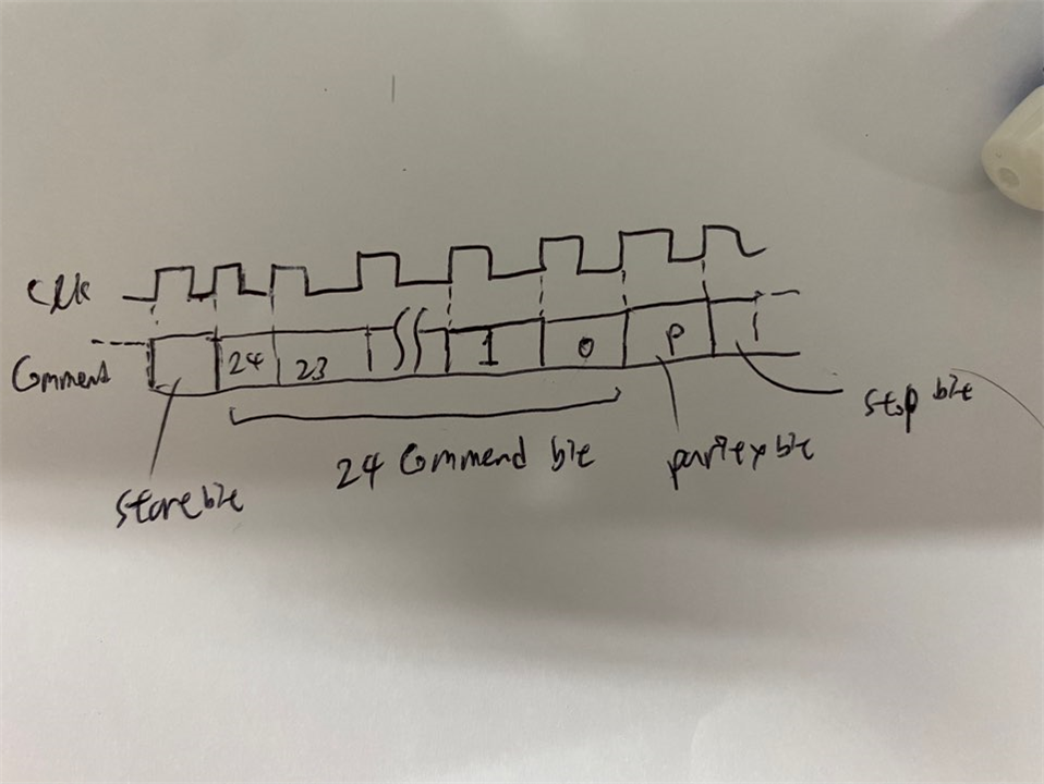
I need to generate 24bits every rising rising edge of 8MHz clk. Like 0101 1001 0000 0000 0010 0000(24 zeros and ones) should be generated every rising edge of 8MHz clk. Every commends on the manual have different configuration of 0 and 1, so i was trying to make function that can determine 0 or 1 every rising edge so that it can express all commends.

I made a clk with pigpio library's " hardware_clock(gpio, clkfreq) " function and used "event_callback(event, func)", i referred "">abyz.me.uk/.../python.html" to use it , to detect the rising edge and call function sending a bit every event(when rising edge is detected). But i found it doesn't work since its operation time was too low compare to clk period. So i tried to use interrupt function of raspberry itself but again found it is slow to use again. Is there any way that i can generate MHz order scale signal using raspberry 4 and python?

So what i want to know since the receiver operates when 8MHz clk and signal are received and synchronized well each other, i want make raspberry operates a function(this would be something like one bit generating) at least 10^-7 second(~ 8MHz) a once.

If needed i may use C language instead, but i am not familiar with it. If it is possible i prefer to use python.

p.s
I found functions from RPIgpio and pigpio aren't compatible(I tried to use clk function from pigpio and eventcallback function from rpigipio). Is this because they occupy same registers in raspberry 4(since they have similar function.. ig)? So that they may malfunction while they are used at once.

Thanks for your helps in advance.
Thanks for reading!

  • Sign in to reply
  • Cancel
  • lolants55
    0 lolants55 over 3 years ago in reply to michaelkellett

    How do you know that it is your signal generator that malfunctions and not the reciever, or a data integrity issue in the interconnection ?

    - I have the guaranteed transmitter(i may call it a 'Commend generater') which i am going to substitute. If i connect Commend generater to receiver i can see that receiver operates well, but as i mentioned it malfunctions often. And that transmitter is made of ASIC chips and SMDs(it has some layers of pcbs in it. So i guess that is why it can generate MHz signal as you mentioned as a solution).

    Referring your suggestion, I will try SPI with 32 bits, but if it doesn't work than i should consider using another hardware.

    p.s. Actually i am doing some kind of my own project(improving old test device('Commend generater') in my lab) within undergraduate level. So i may believe receiver and data line it self have no problem(ig that is outside of my level). I have no other tools that can say receiver is wrong. 

    Thank you for pointing right direction. Really helpful! :)

    • Cancel
    • Vote Up +1 Vote Down
    • Sign in to reply
    • Verify Answer
    • Cancel
  • michaelkellett
    0 michaelkellett over 3 years ago in reply to lolants55

    This may be possible with the Raspberry Pi but I'm not sufficiently familar with its SPI hardware top be sure.

    It is common to send 24 or 32 bit words over SPI but SPI is a synchronous interface with a clock signal. The data bits in any single 8 or 16 bit word (the PI can use either word size in SPI) will be sent at a constant rate but there may be a gap between words.

    You need a hardware setup that will send 27 bits (32 would be OK, you could pack with zeros) at a contant clock rate. Some SPI hardware will do this and some won't. You may be able to find a microcontroller with SPI hardware that has constant clock rate with no missing clocks between SPI words but it's not something that data sheets tend to be clear about.

    From previous experiments with RPi it will not be possible to do it with standard IO and software, it just isn't possible to send lots of bits at a constant rate although the PI is fast enough to do 8MHz bursts.

    The only bomb proof way to do this is with hardware or an FPGA.

    How do you know that it is your signal generator that malfunctions and not the reciever, or a data integrity issue in the interconnection ?

    MK

    • Cancel
    • Vote Up +1 Vote Down
    • Sign in to reply
    • Verify Answer
    • Cancel
  • lolants55
    0 lolants55 over 3 years ago in reply to michaelkellett

    Sorry, my elaboration wasn't enough Slight smile

    What i am going to make with raspberry4 is just signal generator, sending specific configuration of 24bits(commend bit)+3bits(start bit, stop bit, parity bit).

    So when i select commend on raspberry4, it will send 27 bits synchronized with 8MHz clk which are already postulated on the manual of receiver(configuration of commend bits are already defined on the manual of receiver. I have to make raspberry4 to generate those commend 24 bits with start bit, stop bit, parity bit).

    And to let you get it straight i need every single bit of signal generated at rising edge of 8MHz clk. So every 1/8*10^-6 second, one bit should be generated.(Those sets of little rectangle and bottom line of clk on image means 1/8*10^-6 second ) 

    The receiving instrument is just a data collecting device. So it receives the commend from raspberry4 and send data with another data line to computer. I already have the signal generating device but i want to substitute it to raspberry 4, because it malfunctions quite often. 

    Thank you :)

    • Cancel
    • Vote Up +1 Vote Down
    • Sign in to reply
    • Verify Answer
    • Cancel
  • geralds
    0 geralds over 3 years ago in reply to colporteur

    HI,

    It's a point of the type of RPi.

    Not 200MHz. The SPI can transmit up to 125MHz with the chip BCM2711.

    Please read this manual on page 17:

    "Again the SPIs themselves have no throughput limitations, in fact they can run with an SPI clock of 125 MHz. But
    doing so requires significant CPU involvement as they have shallow FIFOs and no DMA support."

    https://datasheets.raspberrypi.com/bcm2711/bcm2711-peripherals.pdf

    Raspberry Pi Datasheets

    Best Regards

    Gerald

    ---

    • Cancel
    • Vote Up +2 Vote Down
    • Sign in to reply
    • Verify Answer
    • Cancel
  • colporteur
    0 colporteur over 3 years ago in reply to geralds

    Sorry G, No & Yes? I was trying to confirm my numbers.

    I was looking to determine the frequency of the data signal. Analog or digital waveform is not my concern. The question is "trying to make the signal". Transporting such a signal is another matter for consideration in transmission media.

    I attended my very first HP systems course to learn how to install and configure HP Unix computer system used for weather forecasting. The instructor was providing the rules for terminators on the SCSI bus. The original SCSI bus in a computer was moving data at 100Mhz. I was confused until he indicated the bus speed of 100Mhz. Wait, that is in the radio frequency RF range. Rules for termination on the SCSI bus were no different than the termination in an RF transmission environment.

    My background was RF transmission systems from HF to well past UH. My career path was taking me from electronic system support to computer system administration. Some of the knowledge between careers was transferable between careers.

    Computers move data at giggly hertz all the time. It is only when the data is taken from the bus that I would start to consider transmission media.

    Can you create a 200Mhz digital signal on a Raspberry Pi and if yes can it be exported?

    • Cancel
    • Vote Up +1 Vote Down
    • Sign in to reply
    • Verify Answer
    • Cancel
  • geralds
    0 geralds over 3 years ago in reply to colporteur

    No - not in this way of thinking. Yes in second thinking about.

    But first - the problem you have is signal leakage. Then the square wave becomes a sine wave or it cannot be transmitted through the cable as well may be the signal comes not to the receiver.
    The higher or sharper the slope of the signal, the slower the frequency needs to be to transmit a digital signal and the shorter the cable length needs to be.

    • Cancel
    • Vote Up +2 Vote Down
    • Sign in to reply
    • Verify Answer
    • Cancel
  • colporteur
    0 colporteur over 3 years ago

    image

    I have read your question and napkined this drawing to confirm your explanation and my understanding are the same.

    The data signal (i.e the bits) has a frequency of 200Mhz? 

    • Cancel
    • Vote Up 0 Vote Down
    • Sign in to reply
    • Verify Answer
    • Cancel
  • michaelkellett
    0 michaelkellett over 3 years ago in reply to lolants55

    You still aren't going back far enough Slight smile

    What device will be receiving this message ?

    But you have changed the definition of the problem a little bit.

    I (and I think Gerald and Shabaz) interpreted your first post as needing a 24 bit frame at a frame rate of 8MHz.

    But now I think you want a 24 bit frame at a bit rate of 8MHz. (Frame rate of 1/3 MHz).

    The RPi SPI port can do this easily. RPi general IO could do it but might be hard to code.

    But you will have problems with the recieving device remaining in sync.

    That's why you need to te expalin the problem at a system level.

    MK

    • Cancel
    • Vote Up +2 Vote Down
    • Sign in to reply
    • Verify Answer
    • Cancel
  • geralds
    0 geralds over 3 years ago in reply to lolants55

    Hi 

    Look for SERDES in combination with FPGAs. - Xilinx, Altera, Lattice offer these chips.

    The RPi makes the host.

    You have to create a data frame because of the possible interference in the transmission path.
    All others are not usable.

    And you need a very good cable, e.g. B. Coaxial cable, or much better, you need fiber optic cable, because the transmission of about 200 MHz over a copper cable is very difficult, -> low-pass.

    How long will the transmit/receive length be?

    Best Regards

    Gerald

    ---

    • Cancel
    • Vote Up +1 Vote Down
    • Sign in to reply
    • Verify Answer
    • Cancel
  • lolants55
    0 lolants55 over 3 years ago in reply to michaelkellett

    image

    What i should do is just generate 27 bits(start bit + commend 24bits + parity bit + stop bit as described above!) and one bit is generated every 1 / (8MHz) second (at rising edge).

    When receiver detect 28 consecutive zeros, they distinguish the start of receiving.

    And after clk signal and signals come in they interpret 27 bits and instruct commends which is already postulated in receiver(for example 0000 0000 0000 0000 0000 0000 means do nothing) and go on.

    • Cancel
    • Vote Up 0 Vote Down
    • Sign in to reply
    • Verify Answer
    • Cancel
>
element14 Community

element14 is the first online community specifically for engineers. Connect with your peers and get expert answers to your questions.

  • Members
  • Learn
  • Technologies
  • Challenges & Projects
  • Products
  • Store
  • About Us
  • Feedback & Support
  • FAQs
  • Terms of Use
  • Privacy Policy
  • Legal and Copyright Notices
  • Sitemap
  • Cookies

An Avnet Company © 2025 Premier Farnell Limited. All Rights Reserved.

Premier Farnell Ltd, registered in England and Wales (no 00876412), registered office: Farnell House, Forge Lane, Leeds LS12 2NE.

ICP 备案号 10220084.

Follow element14

  • X
  • Facebook
  • linkedin
  • YouTube