


In this Upgrade Project, I Have provided the following parameters
1. SpO2
2. IR Temperature Sensor
3. LCD Display
4. Voice Broadcasting
5. Data Saving For Future ML Training
I added the basic details of different Classifications of blood pressure for adults (18 years and older). I will utilize the same chart to create this Project.
Block Diagram Of the Project

I will Explain How To Interface The Sensor With the Raspberry and How to Process to Display the Output. By following this blog You can find what are the libraries and Software settings need to configure for the project.
By using This project you can measure Blood Pressure, Non-Contact IR Temperature Measurement, and SpO2. All these results are displayed on LCD and the Results are Broadcast through Voice. Based on the Accent you required you can change your Voice Broadcast Accent.
Blood Pressure sensor Interfacing With Raspberry Pi
I have used Python 3 for writing code for this project. I have used Python Idle3 to write and Run The code. By default, Raspberry Pi Will have Thonny IDE. If you want to use the same IDE as mine you need to download it by typing the following command in the Raspberry Pi terminal.
sudo apt-get install idle3The BP Sensor Exchanges the Data Over the UART Terminal in Half Duplex Mode. This sensor Communicates the Raspberry Pi by 9600 Baud Rate. To receive the data In the Raspberry Pi We need to Configure UART Channel in the Raspberry Pi.
Raspberry Pi UART
Raspberry Pi has two in-built UART which are as follows:
- PL011 UART
- mini UART
PL011 UART is an ARM-based UART. This UART has better throughput than mini UART. In Raspberry Pi 3, mini UART is used for Linux console output whereas PL011 is connected to the Onboard Bluetooth module. And in the other versions of Raspberry Pi, PL011 is used for Linux console output.
Mini UART uses the frequency which is linked to the core frequency of the GPU. So as the GPU core frequency changes, the frequency of UART will also change which in turn will change the baud rate for UART. This makes the mini UART unstable which may lead to data loss or corruption. To make mini UART stable, fix the core frequency. mini UART doesn’t have parity support.
The PL011 is a stable and high-performance UART. For better and more effective communication use PL011 UART instead of mini UART.
It is recommended to enable the UART of Raspberry Pi for serial communication. Otherwise, we cannot communicate serially as UART ports are used for Linux console output and Bluetooth module.
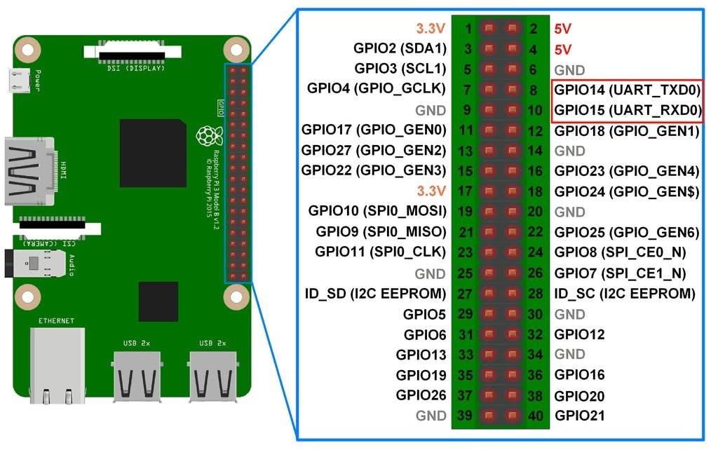
Raspberry Pi 3 UART Pins
Configure UART on Raspberry Pi
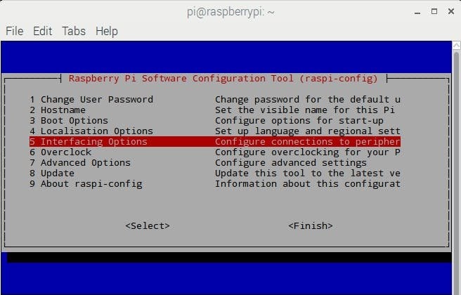
In Raspberry Pi, enter the following command in the Terminal window to enable UART,
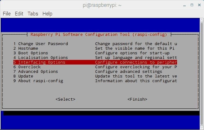
sudo raspi-configSelect -> Interfacing Options
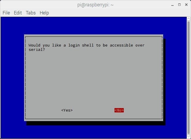
After selecting the Interfacing option, select the Serial option to enable UART

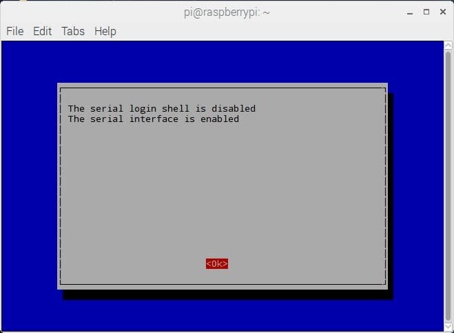
Then it will ask for the login shell to be accessible over Serial, select No shown as follows.
In the end, it will ask for enabling the Hardware Serial port, select Yes,
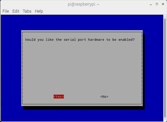
Finally, our UART is enabled for Serial Communication on the RX and TX pins of Raspberry Pi
Then, reboot the Raspberry Pi.
Serial Port for UART Communication
By default, mini UART is mapped to UART pins (TX and RX) while PL011 is connected to the onboard Bluetooth module on Raspberry Pi 3.
In the previous versions of Raspberry Pi models, PL011 is used for Linux Console output (mapped to UART pins) and no onboard Bluetooth module exists.
After making the above configuration, UART can be used at UART pins (GPIO14 and GPIO15).
To access mini UART in Raspberry Pi 3, the ttyS0 port is assigned. And to access PL011 in Raspberry Pi 3 ttyAMA0 port is assigned. But in other models of Raspberry Pi, there is only the ttyAMA0 port is accessible.
Hardware UART port i.e. GPIO14(TXD) and GPIO15 (RXD) is also known as serial0 while other UART port connected to the Bluetooth module is known as serial1. These names are created as serial aliases for Raspberry Pi version portability.
We can check which UART i.e. mini UART (ttyS0) or PL011 UART (ttyAMA0) is mapped to UART pins (GPIO14 and GPIO15). To check UART mapping, enter the following commands.
ls -l /devThe UART mapping for /dev/ttyS0 and /dev/ttyAMA0 is shown below,

After Enabling the UART we need to activate The Audio output channel. Then we have to Install gTTS (Google Text-to-Speech) to announce the BP Status in voice-over.
gTTS (Google Text-to-Speech )
gTTS (Google Text-to-Speech), a Python library and CLI tool to interface with Google Translate's text-to-speech API. Write spoken mp3 data to a file, a file-like object (byte string) for further audio manipulation, or stdout. Or simply pre-generate Google Translate TTS request URLs to feed to an external program.
Run The Below command in the Raspberry Pi terminal To download the gTTS.
pip install gTTSTo Know More About the gTTS Follow the Link https://gtts.readthedocs.io/en/latest/
after the successful installation of gTTS, we need to add a Manipulate audio with a simple and easy high-level interface, To Manipulate audio In this project, I am using pydub.
Run The Below command in the Raspberry Pi terminal To download the pydub.
pip install pydubTo Know More About the pydub Follow the Link https://pydub.com/
Once all the Mentioned Configurations are made we can Run the BP Sensor Interfacing Code.
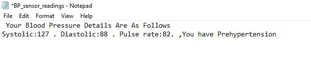
The Output Of the BP Sensor Is saved in the Text Format In Below Figure. You can see the Results Image.
IR Temperature (MLX90614)Sensor Interfacing With Raspberry Pi
To interface the IR temperature sensor we need to enable The I2C and we need to install a few modules.
Enter The command in the Raspberry pi Terminal
sudo apt-get install -y python-smbus
sudo apt-get install -y i2c-tools
install i2c support for the ARM core and Linux kernel. To enable I2C support, We need to enter the configuration Mode of raspberry By Running The Below command in the Raspberry Pi terminal
sudo raspi-config
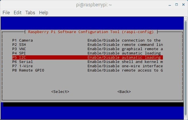
Select Interfacing Configurations
- In the Interfacing option, Select-> I2C

Select Yes when it asks to Reboot.
Now, after booting Raspberry Pi, we can check the user-mode I2C port by entering the following command.
ls /dev/*i2c*then Pi will respond with the name of the i2c port.

Test I2C device on Raspberry Pi
Once the configuration is done correctly Connect The MLX90614 IR Temperature sensor to the Raspberry Pi I2C Pins along with the power pins.
Now when you log in you can type the following command to see all the connected devices
sudo i2cdetect -y 1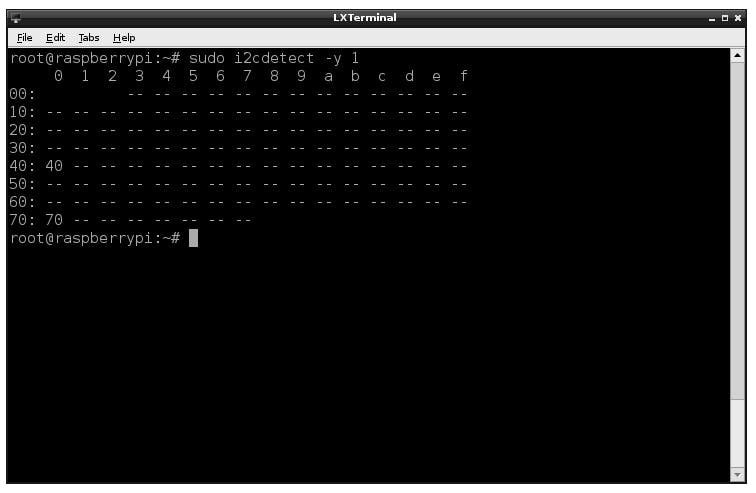
Once all the Mentioned Configurations are made we can Run the IR Temperature Sensor Interfacing With Raspberry Pi Code.
The Output Of the Temperature Sensor Is saved in the Text Format In Below Figure. You can see the Results Image.

SpO2 Sensor Interfacing With Raspberry Pi
To interface the SpO2 With the raspberry pi we use I2C Communication, Since We already Installed All the Required Configuration For I2C, LCD There is no need to enable Them Again. You Just Need To add the Library Called max30102, This Library is modified for the Raspberry Pi based on My requirements. you just need To add those files to the Folder.
The main code is in SpO2 Sensor Interfacing With Raspberry Pi file You need to run this to view the result on the LCD. Before running the code You need to save the hrcalc.py and hrdump.py and max30102.py codes to the folder location as same as the SpO2 Sensor Interfacing With Raspberry Pi code location folder.
In this project, all the above codes run individually you can modify the code to run through a single code.
