element14 Community
element14 Community
    Register Log In
  • Site
  • Search
  • Log In Register
  • About Us
  • Community Hub
    Community Hub
    • What's New on element14
    • Feedback and Support
    • Benefits of Membership
    • Personal Blogs
    • Members Area
    • Achievement Levels
  • Learn
    Learn
    • Ask an Expert
    • eBooks
    • element14 presents
    • Learning Center
    • Tech Spotlight
    • STEM Academy
    • Webinars, Training and Events
    • Learning Groups
  • Technologies
    Technologies
    • 3D Printing
    • FPGA
    • Industrial Automation
    • Internet of Things
    • Power & Energy
    • Sensors
    • Technology Groups
  • Challenges & Projects
    Challenges & Projects
    • Design Challenges
    • element14 presents Projects
    • Project14
    • Arduino Projects
    • Raspberry Pi Projects
    • Project Groups
  • Products
    Products
    • Arduino
    • Avnet Boards Community
    • Dev Tools
    • Manufacturers
    • Multicomp Pro
    • Product Groups
    • Raspberry Pi
    • RoadTests & Reviews
  • Store
    Store
    • Visit Your Store
    • Choose another store...
      • Europe
      •  Austria (German)
      •  Belgium (Dutch, French)
      •  Bulgaria (Bulgarian)
      •  Czech Republic (Czech)
      •  Denmark (Danish)
      •  Estonia (Estonian)
      •  Finland (Finnish)
      •  France (French)
      •  Germany (German)
      •  Hungary (Hungarian)
      •  Ireland
      •  Israel
      •  Italy (Italian)
      •  Latvia (Latvian)
      •  
      •  Lithuania (Lithuanian)
      •  Netherlands (Dutch)
      •  Norway (Norwegian)
      •  Poland (Polish)
      •  Portugal (Portuguese)
      •  Romania (Romanian)
      •  Russia (Russian)
      •  Slovakia (Slovak)
      •  Slovenia (Slovenian)
      •  Spain (Spanish)
      •  Sweden (Swedish)
      •  Switzerland(German, French)
      •  Turkey (Turkish)
      •  United Kingdom
      • Asia Pacific
      •  Australia
      •  China
      •  Hong Kong
      •  India
      •  Korea (Korean)
      •  Malaysia
      •  New Zealand
      •  Philippines
      •  Singapore
      •  Taiwan
      •  Thailand (Thai)
      • Americas
      •  Brazil (Portuguese)
      •  Canada
      •  Mexico (Spanish)
      •  United States
      Can't find the country/region you're looking for? Visit our export site or find a local distributor.
  • Translate
  • Profile
  • Settings
Raspberry Pi Projects
  • Products
  • Raspberry Pi
  • Raspberry Pi Projects
  • More
  • Cancel
Raspberry Pi Projects
Blog Building a Hackaday “Vectorscope” Badge: DIY Guy Fawkes Edition
  • Blog
  • Documents
  • Events
  • Polls
  • Members
  • Mentions
  • Sub-Groups
  • Tags
  • More
  • Cancel
  • New
Join Raspberry Pi Projects to participate - click to join for free!
  • Share
  • More
  • Cancel
Group Actions
  • Group RSS
  • More
  • Cancel
Engagement
  • Author Author: shabaz
  • Date Created: 17 Nov 2023 1:37 AM Date Created
  • Views 2588 views
  • Likes 17 likes
  • Comments 14 comments
  • lcd
  • rpiintermediate
  • tft
  • lcd_display
  • vectorscope
  • raspberry_pi_projects
Related
Recommended

Building a Hackaday “Vectorscope” Badge: DIY Guy Fawkes Edition

shabaz
shabaz
17 Nov 2023

Table of Contents

  • Introduction
  • What Is It?
  • What Parts are Needed?
  • Circuit Diagram
    • How Does it Work?
    • Small Fixes/Changes
  • Proposed Modifications
  • New Ideas?
  • Next Steps


Introduction

I was recently interested in trying out a circular LCD screen for indicating rotational information. I wished to prototype up something that could be used to develop code for circular content on the screen! Searching around, it turned out that some badge developed for a conference used such a display, and a Pi Pico! It looked like a great way to quickly build a development board.

However, unfortunately, that project used a PCB CAD package that isn’t very popular. I’d need to redraw it all into KiCad format.*

The schematic is replicated. Now, there is the opportunity to extend the design a little!

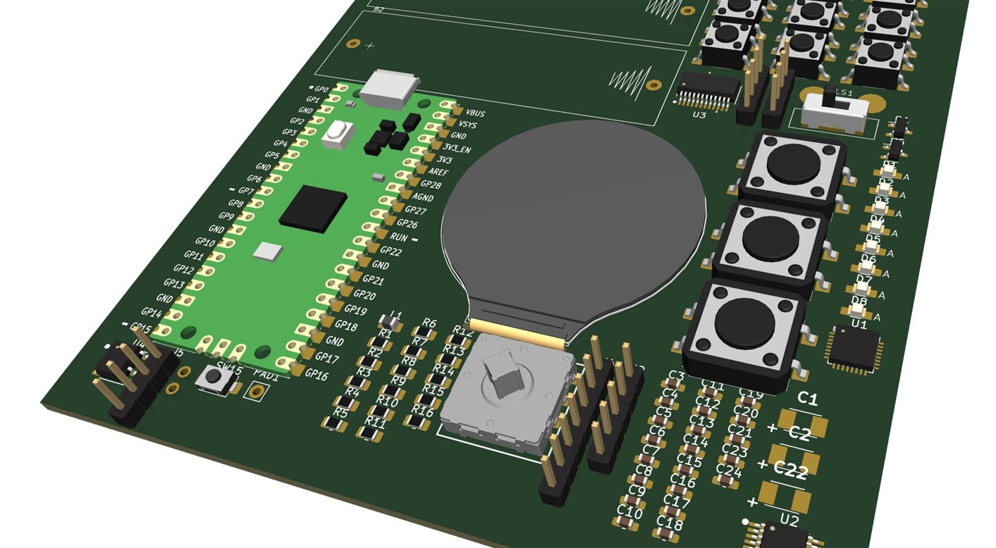
Note: The render below is not how the board will look; I have not done anything with the PCB layout so far. It just shows approximately what components are used on the board!

image

*Note: Since starting it, I’ve realized that other people have given it a shot too, with some based on the original Gerber files. I don’t know their project status since I was unable to view any (perhaps they have not been published yet). Anyway, I decided to continue since if there are faults, there’s just a single throat to choke!

Besides, I wish to make some changes as discussed below. The KiCad files are published on GitHub in case anyone spots errors or wishes to make their own changes. This version does not rely on the original board Gerber files (mainly because I didn't know how to do that). I figured I may as well enter it all into KiCad from scratch, since it's not a huge project.

What Is It?

The original conference board (also see its original GitHub page) is intended for hacking. It is named a Vectorscope, and as such, it contains a couple of ADC channels for capturing data that could be shown in a vector format (although most examples don't do that; it's just a fun badge, after all). Although I don’t need the ADC/DAC, I left that part in the schematic since it could be handy for future projects. Besides, it would still be fun to explore the ADC/DAC in spare time.

image Image source: https://github.com/Hack-a-Day/Vectorscope 


What Parts are Needed?

All the parts are generally available from various distributors, and many of the parts used are jellybean. The LCD screen is available from AliExpress (I don’t know where else to source it from at a reasonable price). All the components will cost 25 GBP / 31 USD at current prices (excluding tax/shipping and PCB). It’s an acceptable price for the functionality. However, since this is a custom board, removing functionality if it is not required can save cost! In my case, I don’t require the ADC/DAC as mentioned.

The entire parts list is below.

Item

Qty

Reference(s)

Value

Notes

1

2

B1, B2

Keystone 2460

Battery Holder Keystone 2460

2

3

C1, C2, C22

22u 16V

22uF Tant Case B

3

10

C3, C4, C10, C11, C13, C17, C18, C19, C20, C24

100n

Cap 0603 X7R

4

11

C5, C6, C7, C8, C9, C12, C14, C15, C16, C21, C23

2.2u 16V

Cap 0603 X5R

5

8

D1, D2, D3, D4, D5, D6, D7, D8

APT2012SYCK/J3-PRV

LED Yellow 0805

6

1

DISP1

ATM0128B1

Round TFT

7

2

J1, J3

Pin-Header-4way

4-pin Header Pins 2.54mm Right-Angle

8

1

J2

Pin-Header-5way

5-pin Header Pins 2.54mm Right-Angle

9

1

J4

Pin-Header-7way

7-pin Header Pins 2.54mm Right-Angle

10

1

J5

Pin-Socket-2x2

2x2 Header Socket 2.54mm Vertical

11

1

L1

47uH

0805 Inductor

12

1

LS1

Speaker

20mm dia 8 ohm

13

1

Q1

DMG2305UX

MOSFET P-ch SOT-23

14

1

R1

22R

0805 Resistor

15

3

R2, R12, R13

2.7k

0805 Resistor

16

4

R3, R5, R6, R7

4.7k

0805 Resistor

17

1

R4

22k

0805 Resistor

18

1

R8

33R

0805 Resistor

19

3

R9, R10, R11

680R

0805 Resistor

20

1

R14

10k

0805 Resistor

21

1

R15

220k

0805 Resistor

22

1

R16

100R

0805 Resistor

23

9

SW1, SW2, SW3, SW4, SW5, SW6, SW7, SW8, SW9

PTS645SK50SMTR92LFS

Tact Switch 6x6mm SMD

24

3

SW10, SW11, SW12

TL3300DF260Q

Tact Switch 12x12mm SMD

25

1

SW13

2425755-1

TE Connectivity Switch 5-way Joystick

26

1

SW14

EG 1218

SPDT Switch 2.5 mm pin pitch

27

1

SW15

Tact 4x3

Tact Switch 4x3 mm body SMD

28

1

U1

AK4619

CODEC (ADC/DAC)

29

1

U2

LMV324

TSSOP Quad Op Amp

30

1

U3

TLC59283

SSOP24 LED Driver

31

1

U4

TPA321

SOIC-8 Audio Amplifier

32

1

U5

Pi Pico

Pi Pico Board

33

1

U6

LM4040C30

3.0V Shunt Reference SOT-23

Circuit Diagram

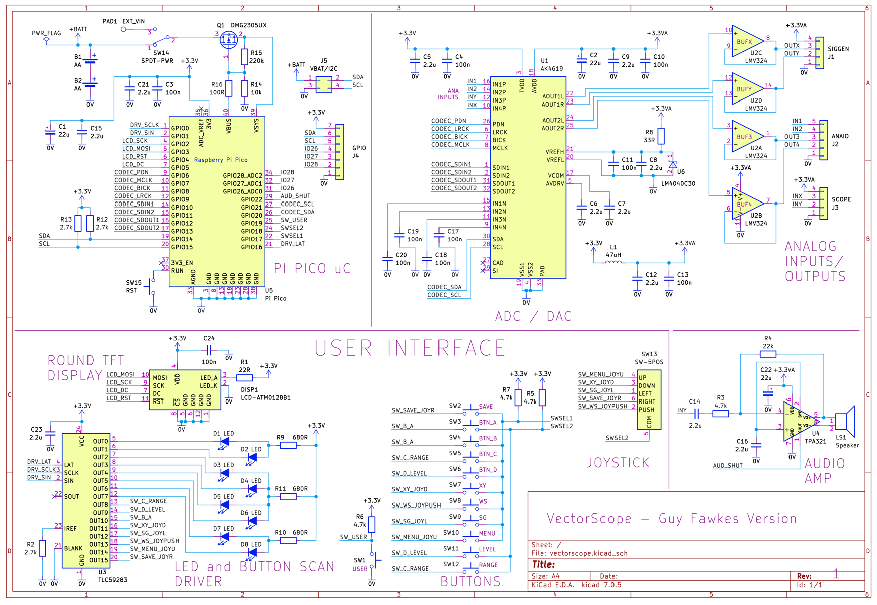
The KiCad schematic is shown below, also downloadable as a high-res schematic on GitHub. If anyone is willing to check it, it would be appreciated, since I may have made mistakes. All the component references are the same as the original conference version (which is available as JPG images, original schematic part 1, and original schematic part 2).

image

How Does it Work?

As can be seen, the circuit is quite simple but nevertheless allows for a lot of experimentation! Here's a quick explanation from the top-left on the schematic, going counter-clockwise:

The Pi Pico is operated from two AA batteries or from USB power. 

The round TFT screen uses an SPI interface to accept data from the Pi Pico. There are 8 LEDs on the board, and they are driven by 8 channels of a 16-channel LED driver chip. The remaining 8 channels are used for scanning an 8x2 array of buttons. This isn't pretty for the source code to manage, but it's cheap and makes total sense for a badge for that reason. Personally, I would really like to modify this part of the design but will refrain so that the original code can be used. I will add any alternative hardware to an extension board instead.

An audio amplifier is wired to an input called INY. An audio codec chip, U1, provides the ADC and DAC functionality. The DAC outputs are connected to op-amp buffers. 

Small Fixes/Changes

For this KiCad version (let’s call it the Guy Fawkes version for want of a better name, since others may produce other KiCad designs, and this KiCad version was produced in November), I added a few minor parts, mainly capacitors, since there’s less need to cost-reduce since I’m not producing this in the hundreds as the conference badge was.

I corrected a MOSFET issue that was on the original board and also decided to add a few resistors to protect the MOSFET a bit (the original conference badge version doesn’t need that since the MOSFET is in-circuit, but for a DIY version, there will be times when the Pi Pico is not attached, and that makes the MOSFET out-of-circuit if the protection was not added). Otherwise, the circuit should be identical for now unless I’ve made errors!


Proposed Modifications

Since I don’t need the ADC/DAC, I plan to bring out the GPIO pins onto the edge of the board so I can use them for attaching extra circuitry (such as a rotary encoder). The ADC/DAC consumes a lot of pins on the Pi Pico (10 pins), so I want to use them for off-board purposes if the ADC/DAC chip is not soldered on. Even if the chip is soldered on, the edge connections could be useful for probing the chip.

New Ideas?

If you have ideas for the board, it would be great to hear them. I don’t want to make too many changes from the original board so that the existing software can be used, but I’d still be interested to hear suggestions. I was thinking about adding optional circuitry for an I2C real-time clock (RTC) chip so that the board can function as a desk clock.

Next Steps

The Vectorscope, although intended as a fun conference badge, could be excellent for learning about various hardware components and software! I think it will also be useful for anyone who wishes to design a circular GUI, display rotational/angular/vector information, or even just to build a fancy clock.

I have started laying out the PCB design and will likely submit the PCB order within about a week or so. It will be a fun project to assemble over the Xmas hols. If you’re interested in building one, the KiCad files are on GitHub, but as mentioned, the PCB layout is still to be done, so you may wish to wait, or you could use the original Hackaday Gerber files. But if you wish to influence this KiCad design a bit, please let me know!  

Thanks for reading!

  • Sign in to reply
  • shabaz
    shabaz over 1 year ago in reply to RobinJFMcBurnie

    Thanks for the comments!

    I too agree, support for Pico W is super-important requirement for this board. I'm planning to leave off a portion of ground plane so that the Pico W can be used. I would have gone with NeoPixels, but then any existing code for the VectorScope board will need modification. That part of the board doesn't use too many pins (it's using an I/O expander, along with buttons interfaced to it too) so I may leave that for now. The thing that's consuming up most GPIO is the ADC/DAC unfortunately : (

    I2S mic or audio output is an excellent idea. I'll have to think about that, see if I can multiplex anything. 

    I've not had as much time as desired to work on this, but I'm hoping to get to the PCB work soon!

    • Cancel
    • Vote Up 0 Vote Down
    • Sign in to reply
    • More
    • Cancel
  • RobinJFMcBurnie
    RobinJFMcBurnie over 1 year ago

    I love those round displays!

    Ever since the AdaFruit "Halloween Eye" project I've also wondered about other uses for the round displays.

    Depending on how far along you are with this project, I would suggest changing the Pico for a PicoW. As the BLE is now (mostly) useable, it opens up possibilities at conferences / Hacker Meets, etc. We have used similar to "broadcast" (over < 5 metres) our personal interests. This can interact with similar badges with BLE enabled. It also works with Mobile phones, although apps are a bit cludgy at present.

    The idea is that the badge(s) direct their wearers towards the nearest person with interests in common. Done right, you can have the badge indicate with a sequence of concentric circles as you get closer. Sometimes you get a small group! Ideally you should have a button programmed such that when 2 people who are within the correct distance and have been for a (choose apropriately) specified time press their buttons at the same time, contact details are exchanged (which you can upload to your laptop at you leisure).

    Also to save pins I would suggest NeoPixels (Needs to use one of the PIO Blocks) or the SPI (Needs One SPI Port - SCK and DO) version for the Led's. This takes either 1 (NeoPixels) or 2 (SPI) pins on the Pico. Likewise by using a resistor ladder (you might need two, one for each set of 8 Buttons. If you can get reliable resutls with a single 16 resistor ladder, then you only need one of the Pico ADC inputs to read which button is pressed. Of course this only likes one button to be pressed at any time.

    Perhaps an I2S MEMS mic for input and one of those I2S Digital amps for audio out to the speaker?

    As there are already libraries for almost all of the above, the software should not be too difficult to implement.

    As an aside, this is battery-powered, is there really a need for a second battery backup for the RTC or just a SuperCap to keep the (Pico Internal) RTC going during battery replacement.

    Thank-you for putting the KiCad files up on GitHub. They provide an excellent staring point.

    A very Interesting project overall, I just like trying to reduce external components and make as much use of the power of the pico itself - I see that as part of the challenge!

    • Cancel
    • Vote Up 0 Vote Down
    • Sign in to reply
    • More
    • Cancel
  • shabaz
    shabaz over 1 year ago in reply to shabaz

    Squeezed in a RTC into the circuit (I like to print them, so I refuse to move the schematic from a single A4 sheet : ). This RTC was cheap and available, and should run for a few years on a small coin cell. 

    image

    • Cancel
    • Vote Up 0 Vote Down
    • Sign in to reply
    • More
    • Cancel
  • fmilburn
    fmilburn over 1 year ago in reply to shabaz

    The binder idea is clever. That would be a good way to show it off as well as give protection. I am away from home but I think what I generally use is ~3.2 mm holes because I have threaded brass inserts for 3mm screws. But holes for 2mm would work, would just have to be threaded into the plastic or a captured nut instead of a fancy insert.  I’ve been wanting to play with one of those round displays every since I first saw them.

    edit: at least one hole offset from the ones in a line would be good for pcb stability if mounted

    • Cancel
    • Vote Up 0 Vote Down
    • Sign in to reply
    • More
    • Cancel
  • shabaz
    shabaz over 1 year ago in reply to fmilburn

    Hi Frank,

    That's a good idea. Let me know if there's any particular holes that are preferred, e.g. just plain 2mm or 3mm holes?

    I'll make sure to place all holes and buttons etc at round number locations (e.g. 5mm, 10mm etc), so that they are easy to enter into the 3D CAD software.

    I had a semi-baked idea of maybe adding holes to one side of it, so that it can fit into a small ring-binder (they come in a small A6 size which is 105x149mm which is more than enough) and then there's plenty of access for USB connection, changing out battery, even some storage space for notes of course!  or jumper wires : ) There are all sorts of them and they are low-cost. I think the batteries would need to move to the far end though, to easily allow it to fit in the binder rings.

    It might not be everyone's cup of tea, so I could try the binder layout later, as an alternate form-factor option. 

    image

    • Cancel
    • Vote Up 0 Vote Down
    • Sign in to reply
    • More
    • Cancel
>
element14 Community

element14 is the first online community specifically for engineers. Connect with your peers and get expert answers to your questions.

  • Members
  • Learn
  • Technologies
  • Challenges & Projects
  • Products
  • Store
  • About Us
  • Feedback & Support
  • FAQs
  • Terms of Use
  • Privacy Policy
  • Legal and Copyright Notices
  • Sitemap
  • Cookies

An Avnet Company © 2025 Premier Farnell Limited. All Rights Reserved.

Premier Farnell Ltd, registered in England and Wales (no 00876412), registered office: Farnell House, Forge Lane, Leeds LS12 2NE.

ICP 备案号 10220084.

Follow element14

  • X
  • Facebook
  • linkedin
  • YouTube