


Table of Contents
Introduction
This blog post discusses how to make a signal generator using an off-the-shelf low-cost transceiver module plus a Pi Pico microcontroller.
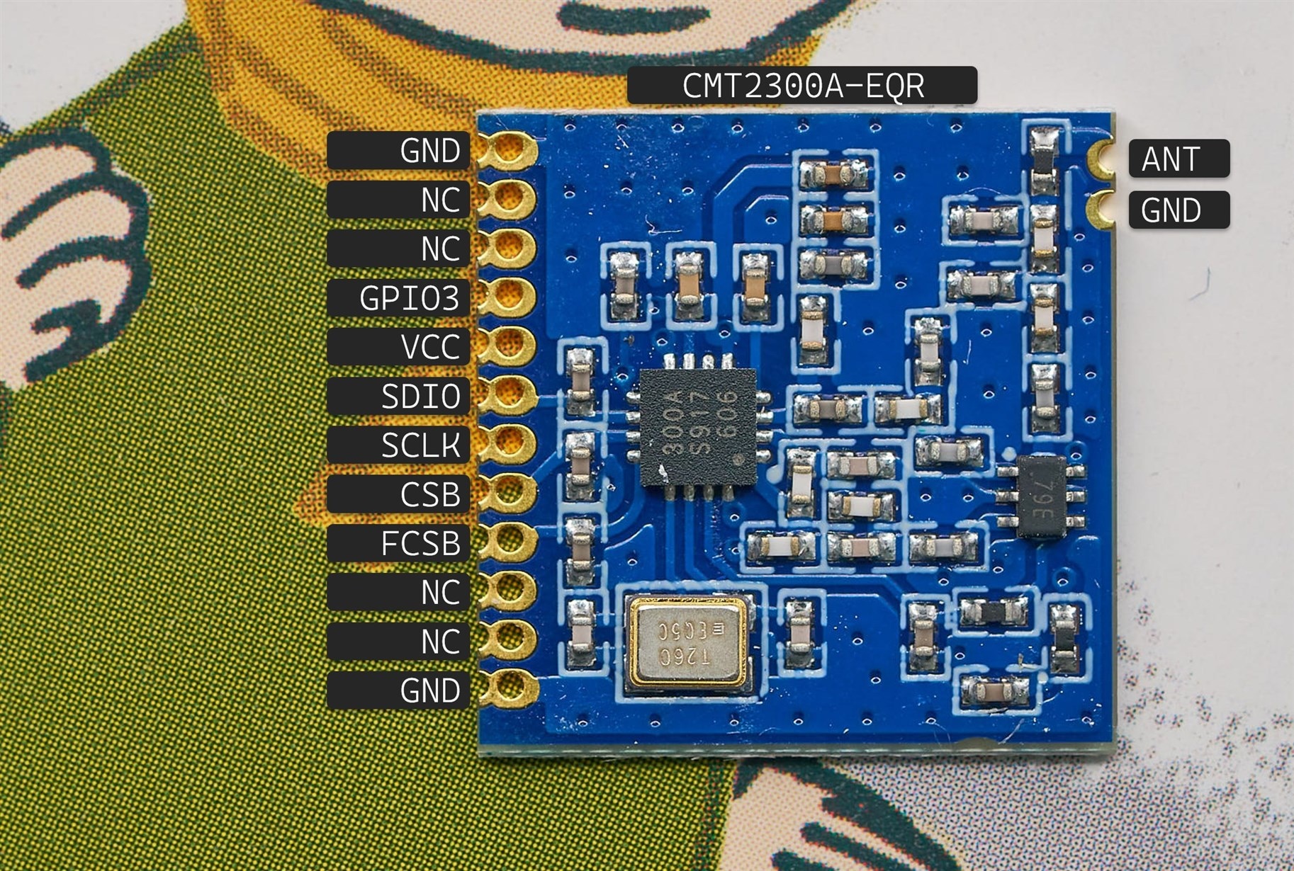
This is a simple two-component project; a CMT2300A module, and a Pi Pico. The desired frequency is selected via USB (a USB Serial menu), but in future, buttons and a display could be attached if desired.
Motivation
Recently, an interesting topic came up on the Element14 site; how could a 433 MHz transmitter output be easily viewed using an instrument that only works up to 60 MHz?
One popular method is called down-conversion. A three-port device called an RF Mixer is utilized. The mixer has two inputs (labelled RF and LO) and an output (IF). Mixers are available as ready-made modules, or they could DIY’d. Here is an example of one:
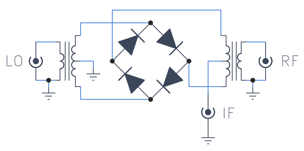
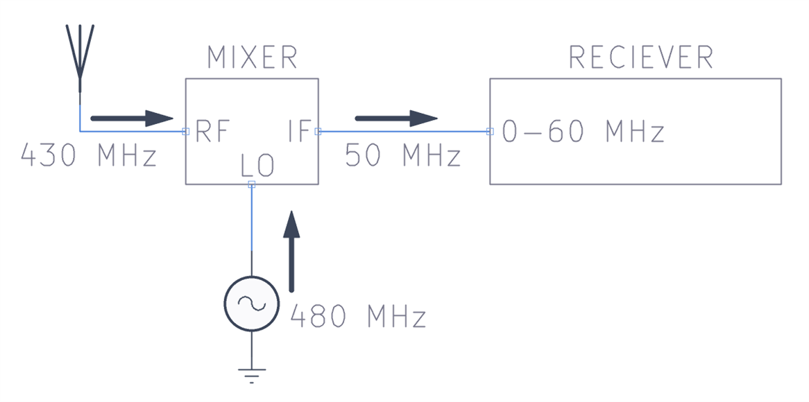
Mixers have the property that the IF output contains the sum, and the difference of the frequencies present at the other two ports. The diagram here shows how a mixer could be deployed to solve the problem, because 480 minus 430 provides a 50 MHz signal comfortably within the 60 MHz range of the equipment.
In reality, the IF output would also contain the sum of 910 MHz (plus sometimes a load of other unwanted frequencies, perhaps at much lower levels), but those could be ignored by the receiving instrument.
Assuming you have a mixer, the problem then shifts to how to create a suitable LO frequency. A traditional method would have been to use an NE602 IC, which contains a built-in oscillator that needed a few components to set and manually trim the frequency. The NE602 is unfortunately obsolete. In addition, one may want a more accurate method to set the frequency these days.
There are digital clock generation ICs such as Si5351, but often they do not support frequencies beyond the low-to-mid VHF range.
RF ICs To the Rescue
I decided to exploit the fact that RF ICs intended for low-power communications for simple remote control or telemetry, might be able to be operated in a continuous-output mode with no modulation applied. Searching around, I decided to try the CMOSTEK/Hope RF CMT2300A, because it is readily available pre-soldered onto a small circuit board with all the necessary parts, all ready to attach to a microcontroller.
I liked that it supported a broad range of frequencies, specifically:
127-169 MHz
190-339 MHz
380-509 MHz
759-1019 MHz
In practise, the 759-1019 MHz range is not recommended with the particular module that I used, at least not unmodified (more on that later).
The module closely follows the circuit in the datasheet:
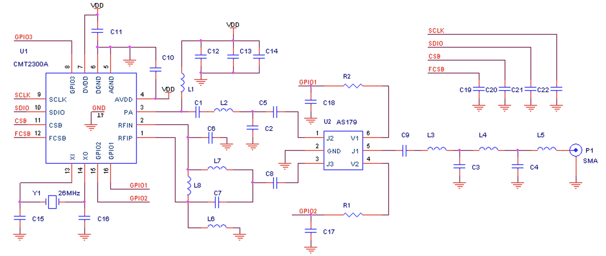
(Image source: CMT2300A datasheet)
I annotated the photo with component references for the RF portion, just in case in future I ever wish to modify it.

The module is very small, and soldering the wires is a bit fiddly. I wired the antenna output to a short length of thin coax that goes to an SMA connector. For testing, I connected that to a spectrum analyzer, but a radio receiver could be used too. Use attenuation, because the output in theory approaches 20 dBm!
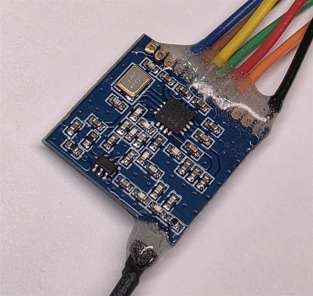
I connected the module to the Pi Pico. The module was powered from the 3.3V output from the Pi Pico (the module consumes around 50 mA).
| Pi Pico | CMT2300A |
| GPIO2 (pin 4) | SCLK |
| GPIO3 (pin 5) | SDIO |
| GPIO4 (pin 6) | CSB |
| GPIO5 (pin 7) | FCSB |
| GPIO6 (pin 9) | IO3 |
| +3.3V (pin 36) | VCC |
| GND (pin 8) | GND |
Software
See the github repo to download the code.
The Hope RF website had example code for STM32, I used bits of that. I used AI to create a user menu that uses set and get commands to control the functionality. The code is written to build using the RP2040 C/C++ SDK (the steps to install the SDK and to build the firmware are not covered here, because that is identical to all the hundreds of Pi Pico SDK examples/tutorials on the Internet).
There is a ready-built firmware file called prebuilt.uf2 that could be immediately used, if there is no desire to compile the code. To install, hold down the BOOT button on the Pi Pico and insert the USB cable into the PC, then release the button. A drive letter will appear, and the .uf2 suffix file can be drag-and-dropped over that drive letter. The firmware will install within a few seconds and start running.
On the PC, a serial port should appear (COM port on Windows, or /dev/ttyUSB0 (or approximately similar) on Linux). Serial terminal software is used; type help in the terminal, to see the list of supported commands.
The screenshot here shows what to type to set the frequency to 440 MHz and turn on the transmitter:
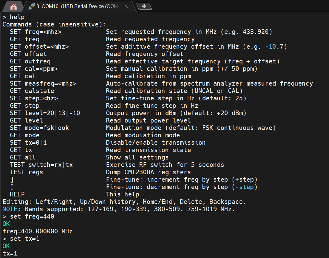
Once transmission is enabled (using set tx=1) then the frequency can be modified at any time by typing the new value (for instance set freq=480.123).
A very useful feature in my opinion is the ability to calibrate. For example, after setting to any desired frequency, if equipment can be used to measure the actual frequency, then the set measfreq=480.123456 command can be used to notify the software. It will calculate the crystal oscillator error in parts per million (ppm) and display that, and all future set freq commands will apply the calibration.
The calibration doesn’t survive a reset; I have not implemented non-volatile memory for now (if you add that before I get around to it, please submit your changes so that they can be added to the project GitHub repository).
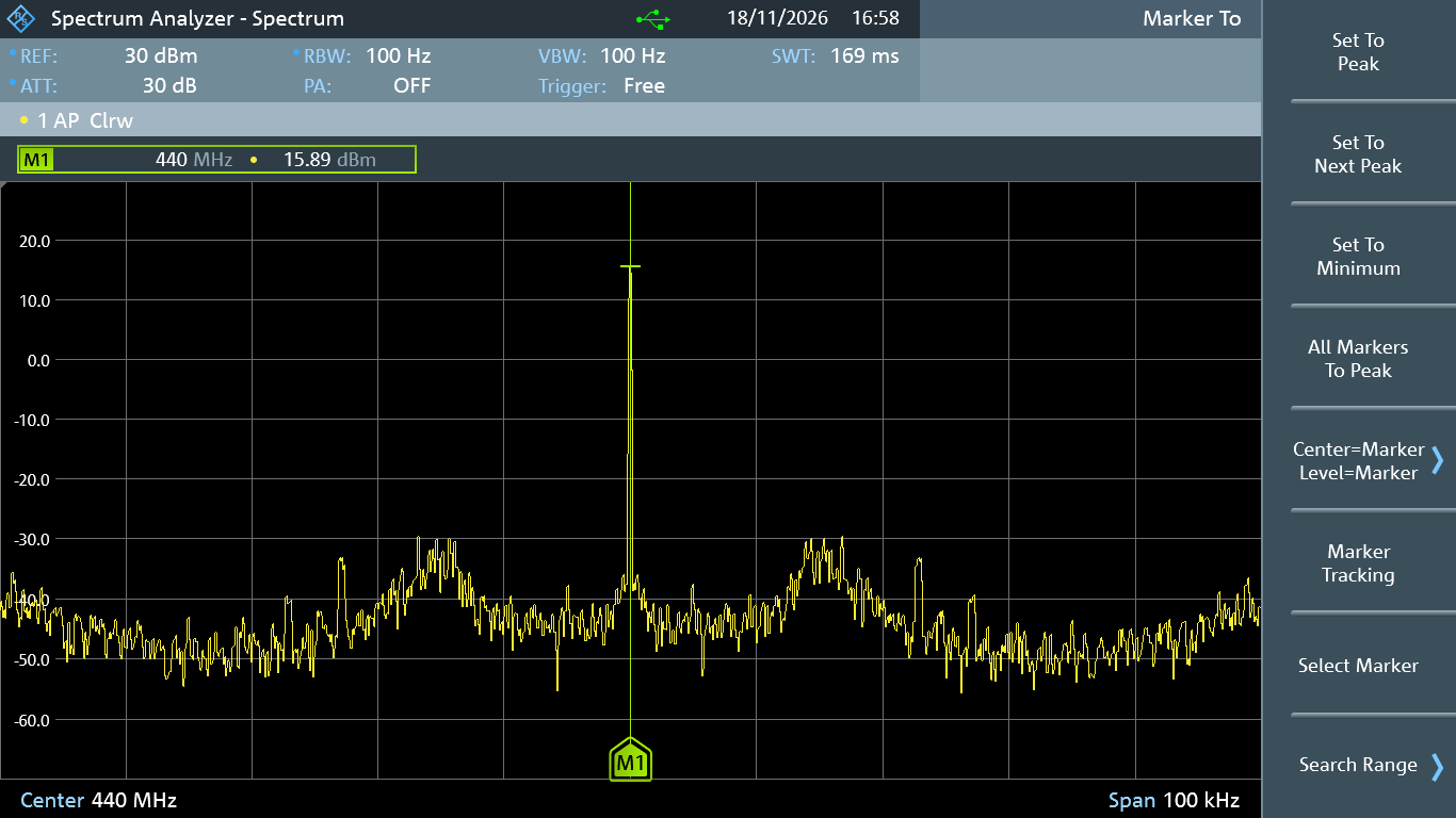
My CMT2300A module happened to be out by around +20 ppm, but with calibration, the 440 MHz output was just off by 85 Hz:

To interpret that screenshot above; the entire spectrum shown spans 100 kHz, and is centered at the peak output, which was 440.000085 Hz. The power output at that frequency was 15.87 dBm (see the M1 marker).
The CMT2300A supports a resolution of 25 Hz, so it is possible to trim further, to get the output almost dead-on. Press [ or ] in the menu, to shift left/right by 25 Hz. Hold the key down and watch the output slowly slide left or right. Now the output is reported as 440.0 MHz as seen in the following screenshot:
Results
With the transmission off (set tx=0) the CMT2300A module current consumption was 1.36 mA.
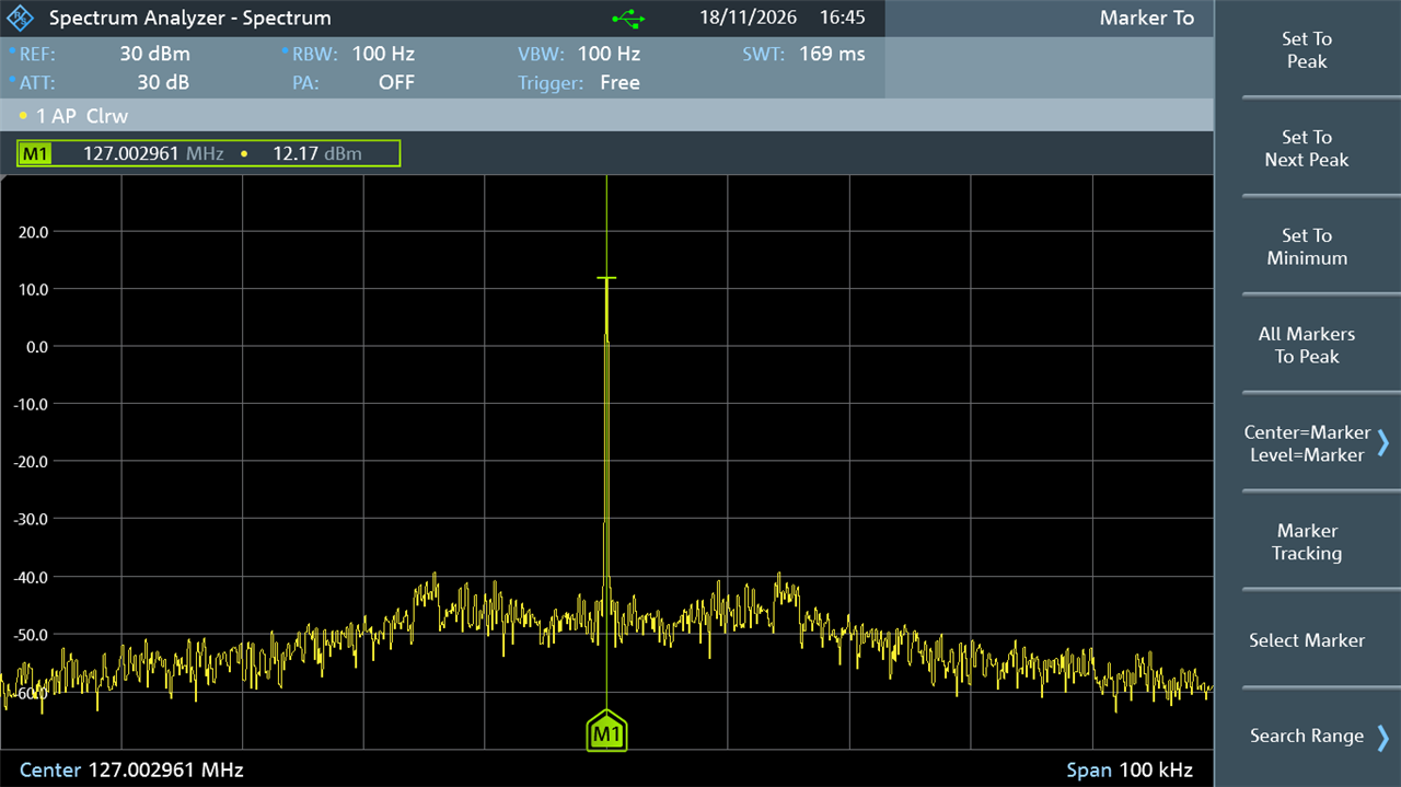
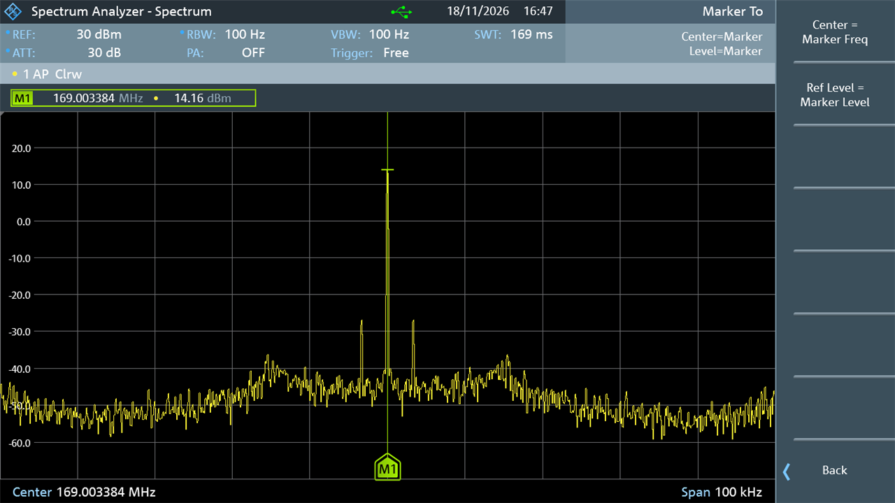
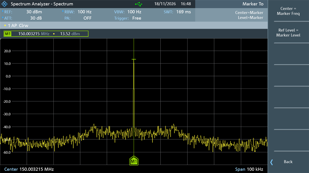
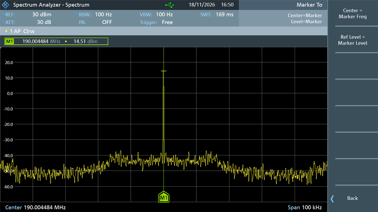
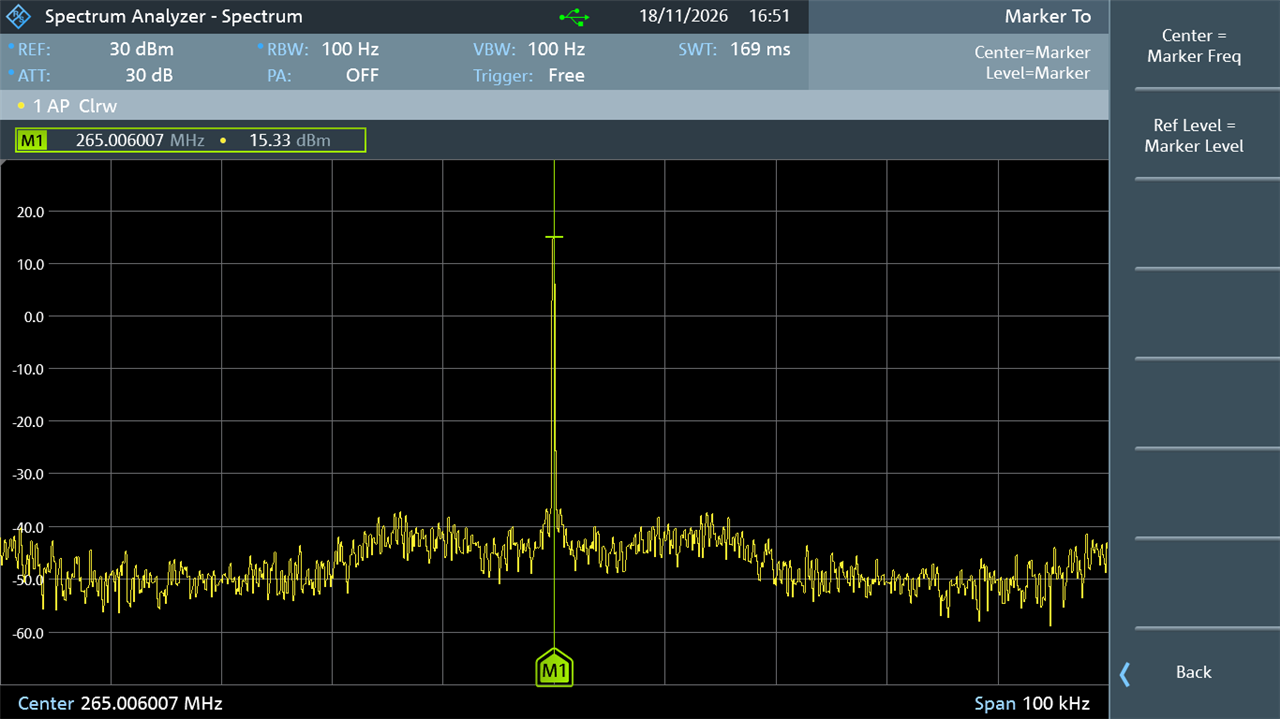
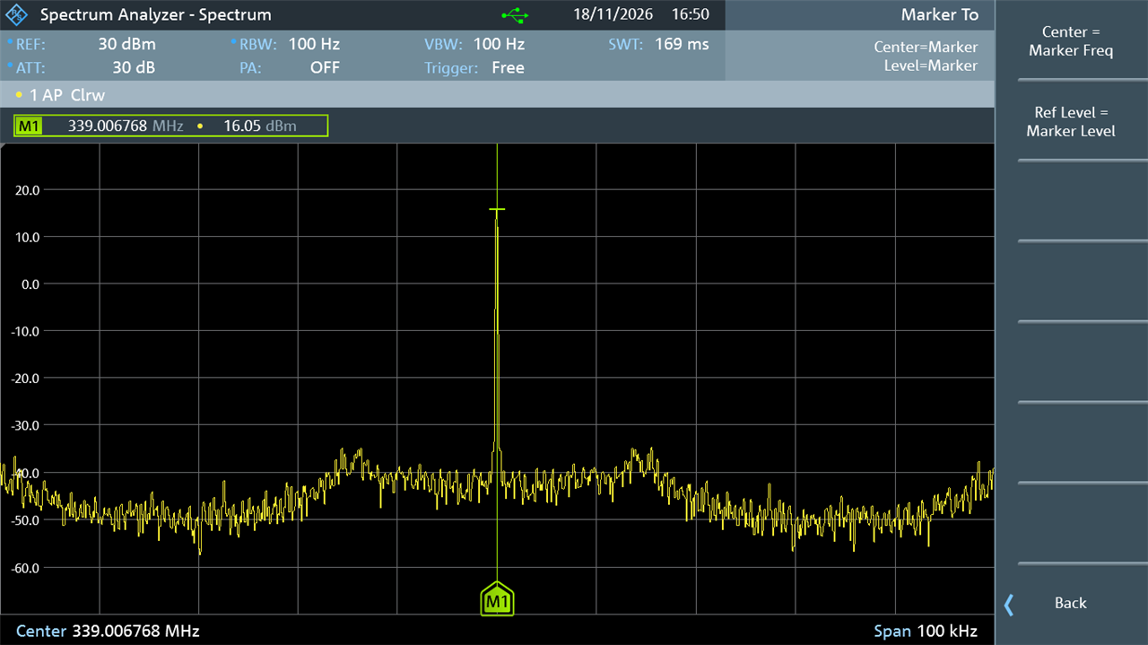
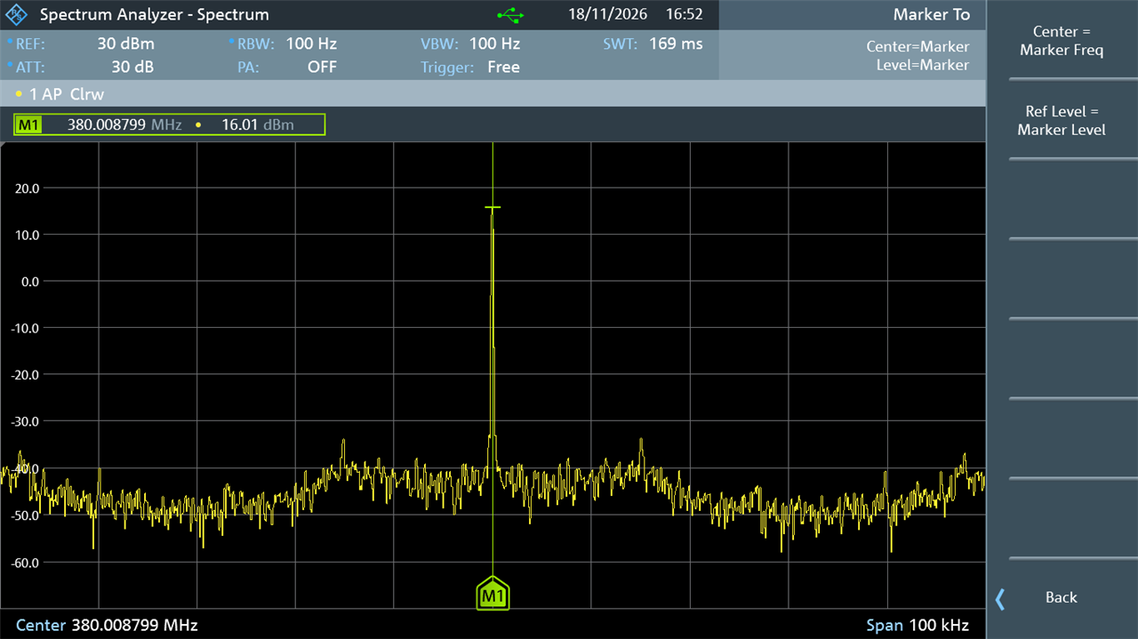
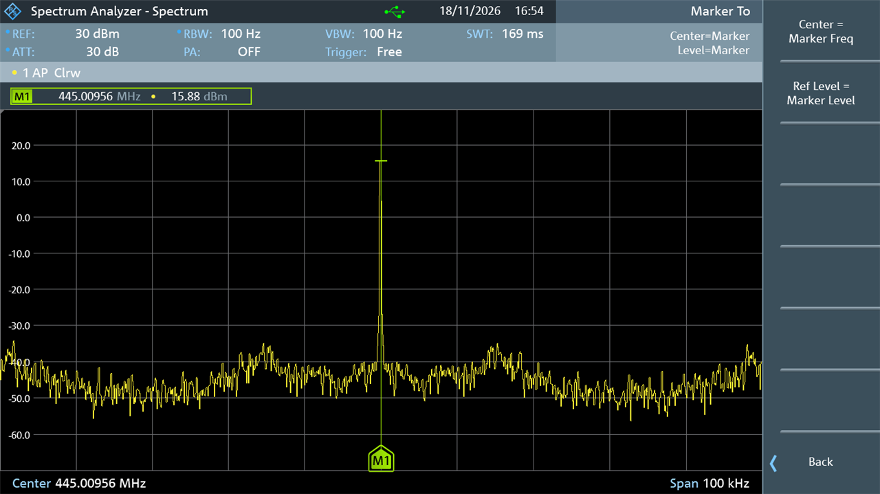
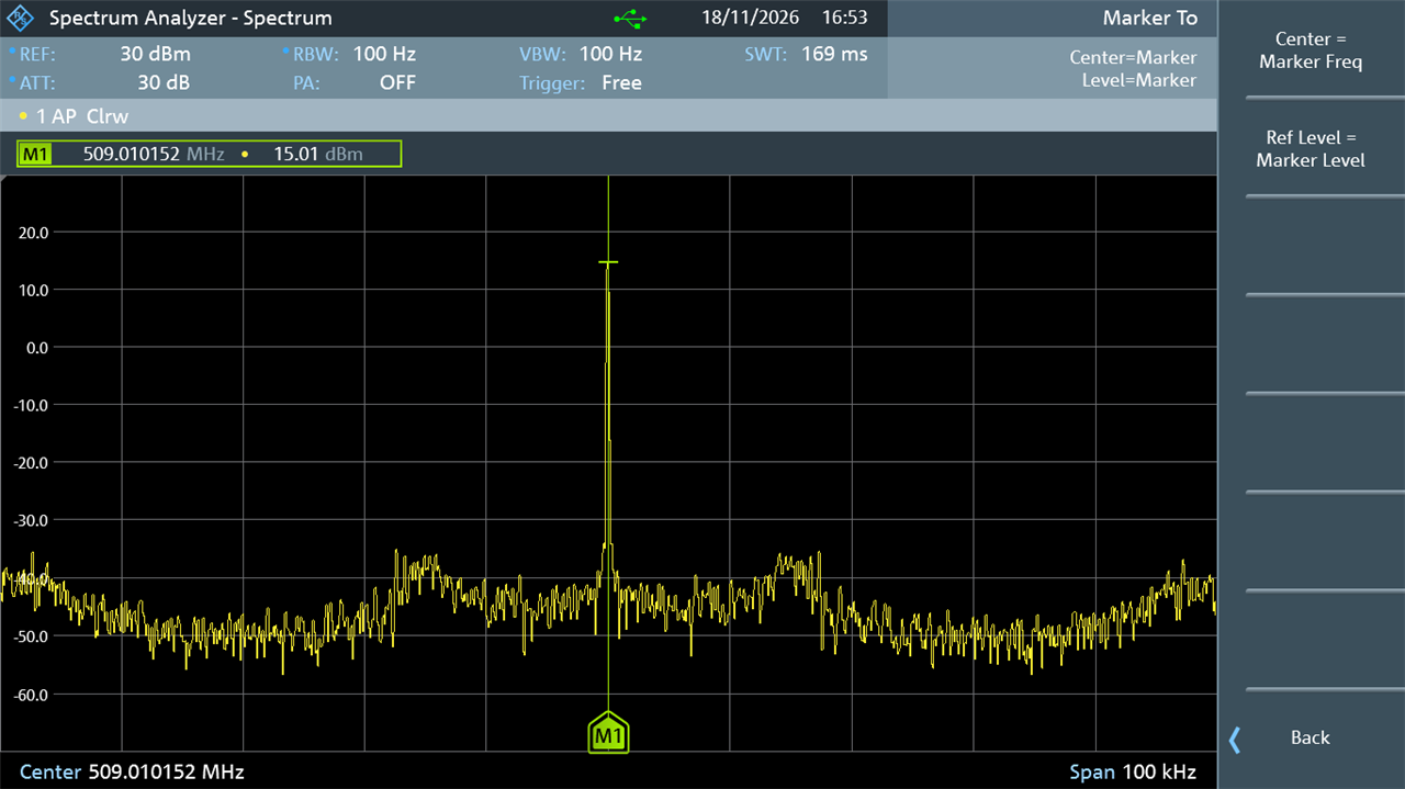
I measured the power level of the desired signal, for a range of frequencies, along with current consumption:
| Freq (MHz) | Output (dBm) | Current (mA) |
| 127 | 12.2 | 28.3 |
| 150 | 13.5 | 36.2 |
| 169 | 14.2 | 41.4 |
| 190 | 14.5 | 45.6 |
| 265 | 15.3 | 50.5 |
| 339 | 16.1 | 48.8 |
| 380 | 16.0 | 48.8 |
| 445 | 15.9 | 50.0 |
| 509 | 15.0 | 39.2 |
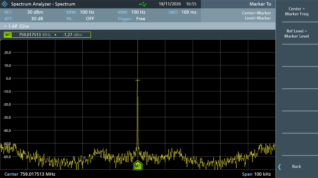
| 759 | -1.27 | 43.0 |
As can be seen, the maximum practical output was about 16.1 dBm. The module is designed for 433 MHz operation, so it is not surprising that the output drops off at extremes. I don’t think it will be wise to operate at 759 MHz upward, because the output level is low, and there is a risk of damage to the module. There is possibly lower risk of damage at the lower frequencies, but I cannot guarantee there will be no issue. The modules are cheap, perhaps one could be left operating for long periods to see what happens.
If operation at 759 MHz or higher is required, a different module should be used, or the components on the module could be replaced (the datasheet would need to be consulted).
For Reference
Output screenshots for reference, click to enlarge:
Summary
A very low-cost CMT2300A 433 MHz RF transceiver module was repurposed to provide an adjustable RF output signal. This could be useful for down-conversion, to observe (for instance) higher-frequency signals on equipment that does not directly support the frequencies of interest. Another use-case could be to build a radio receiver.
It turned out not too difficult to use the CMT2300A, although I made use of AI to help me. A Pi Pico was used to configure the CMT2300A, using a USB Serial based menu system.
It was found that the output is likely usable without any board modifications, except for the upper range (759 MHz upward). However, there is no guarantee that there will not be an issue long-term. The module is being used outside of its intended range, it is designed for the 433 MHz band.
The code is in GitHub, along with a prebuilt firmware file if compiling is not convenient.
Thanks for reading!


