


The Raspberry PiRaspberry Pi has been a huge phenomenon in the maker scene, spawning a wide range of accessories, add-ons and even specialised 'Hats'. One of the most underappreciated peripherals would have to be the small Raspberry Pi camera boardRaspberry Pi camera board. At first look it might seem to be the same as any cheap USB camera, but its functionality is far beyond that. The special 15 pin ribbon cable the camera board uses enables it to interface directly with the graphics processor on a Raspberry Pi. This allows it to use the full power of the Pi for all the image processing and heavy lifting, rather than relying on processors in the camera itself. This, combined with its reasonably high fidelity photo sensor, lets the camera produce great quality images and videos at a reasonably low cost. The other feature of the camera board is its ability to be activated and controlled from various coding languages. There is an extensive library of code for the Python programming language and it can also be used right from terminal in a compatible Linux distribution.
For a project using the camera board, I mounted it along with a Raspberry Pi and a small LCD screen into a car to be used as a DVR system. Car DVRs are very popular tools both for private and commercial vehicles - they are used to provide evidence in resolving traffic disputes and aid in insurance claims. If your car is your pride and joy, having video evidence of a crash can be the difference between getting an insurance payout and being stuck with an expensive wreck.
For this project the Raspberry Pi can be running a number of Operating System. The requirement is that it has to run Python and be compatible with the camera board and GPIO modules. For a quick and easy setup I used a NOOBs pre-loaded microSD cardNOOBs pre-loaded microSD card. It comes pre-loaded so there is no need to format or write an SD card, it's ready to go right out of the box. By holding Shift on a keyboard right after boot you'll get to the recovery menu that will let you choose different operating system. For this project I stuck with the pre-loaded Raspbian.
Depending on the electrical system in your car, powering a Raspberry Pi from it can cause difficulties. When starting the engine or switching on electric devices, such as headlights, the power from the battery or alternator can momentarily drop. Modern car stereos are designed to tolerate this, but the humble Raspberry Pi is not - any significant drop will cause it to fully loose power then reboot. This can be annoying at best, forcing a system reboot every time you want to start the engine or switch the headlights to full beam. A solution to this is using a UPS - Uninterruptable Power Supply.
A UPS works by having a battery that can power devices when incoming current temporarily drops out. My low cost UPS solution was using a super cheap, unbranded, USB Power Bank - small external batteries that are commonly used to charge cell phones on the go. Unfortunately, most of these types of devices aren't the best solution. A normal UPS works by having an ultra fast, automatic switch that can toggle from the incoming power to a battery bank when the current drops below a certain level - switching fast enough that devices attached to the UPS do not notice any difference. Most cheap power banks, however, function by having the input power charge a battery and have the output power coming from the battery simultaneously. Inefficiencies in the battery and the circuitry used to charge it means that the power coming out is significantly less than the power coming in. Because of this some of these devices are unusable as a UPS while others may function but can have issues, such as the battery running flat even when it is being recharged. There are many such devices and each one is different. The brandless one I have functions adequately when powering a Raspberry Pi, but others may not.
The best way to have simple control of the cameras recording functionality is to connect a toggle switch to the GPIO on the Raspberry Pi. By using a GPIO switch to control the camera, you leave any keyboard, mouse or even touchscreen input unused and free for any other use by your chosen operating system. You can use a flick switch or a rocker, but to keep the footprint on the dashboard small I used a latching pushbuttonpushbutton. You may have seen other guides use pull-up resistors for buttons on the Raspberry Pi, but we can use a line of code to pull-up for us. Simply wire one of the button contacts to an available GPIO pin - in my case I chose #24, but any will do - and the other contact to one of the Pi's ground pins. The easiest way to do this is using female jumper wiresfemale jumper wires, just cut the end off two wires and solder them to each of the button contacts.
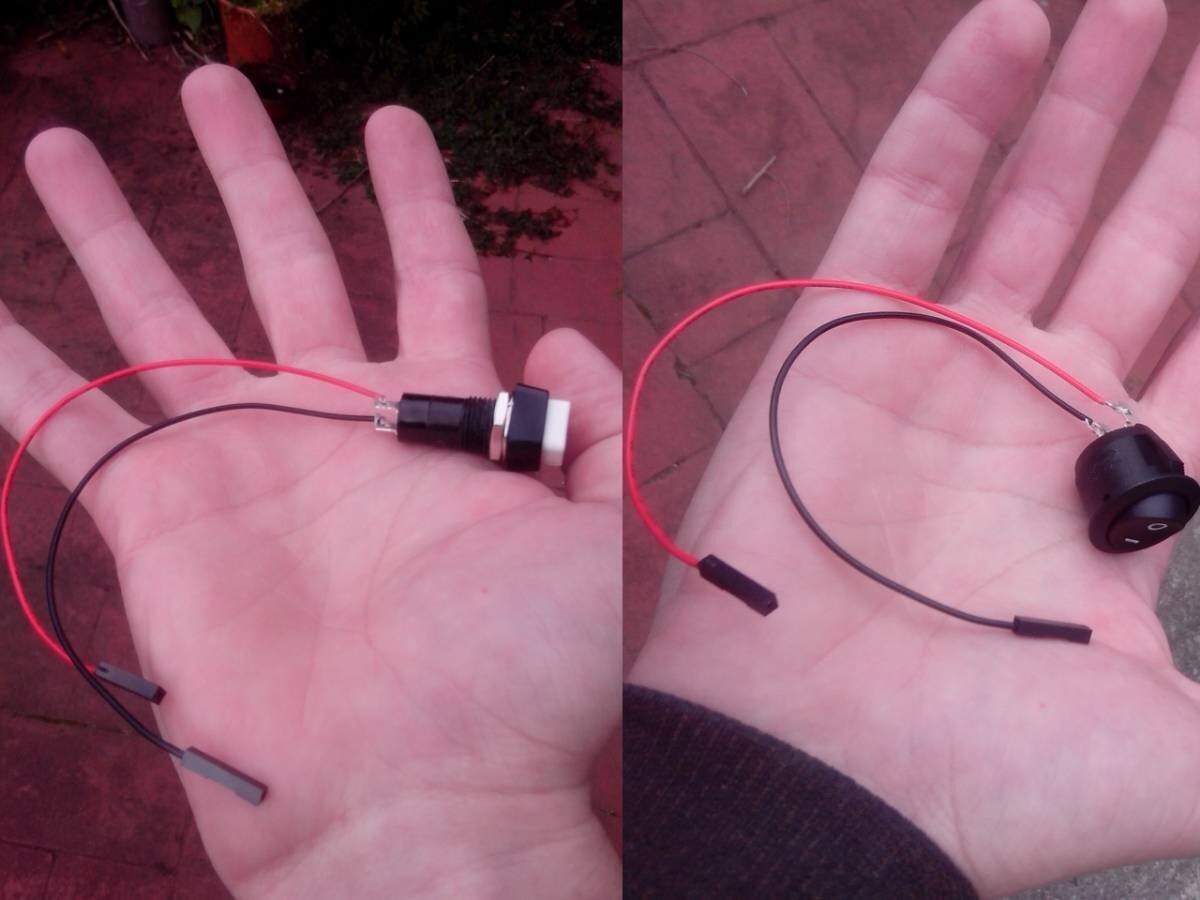
Latching PushbuttonsLatching Pushbuttons and Rocker SwitchesRocker Switches connected to jumper wires
Something that you don't release before seeing it in the flesh is just how small and light the camera board is. My original plan was to use a small piece of acrylic attached to suction cups to make a mount that sticks on the windshield. Unfortunately getting it to hinge on the right angle for a good view while still being solid enough to not wobble while recording was tough. The solution I found was to use a GPS suction mount that has a good hinge, using light adhesive and small screws to stick the camera board to its backside. It was solid enough to not shake while recording but could still be oriented for the best viewing angle out the windshield.
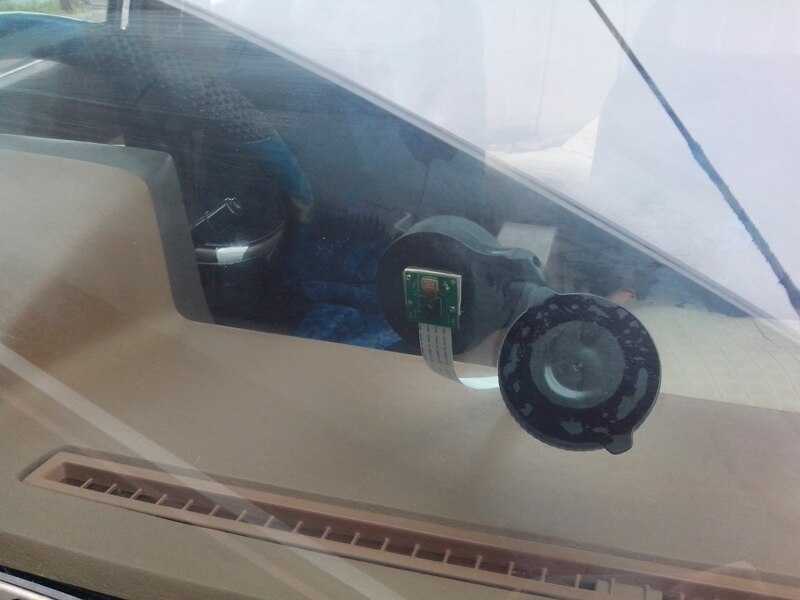
Camera board mounted on the windscreen
When mounting the camera board, be careful to check what your local laws and regulations are. Certain states in the US, including California, have laws against attaching any device to a vehicles windshield even if it is just temporarily adhered with suction cups. Fortunately, here in cold New Zealand no such laws exist.
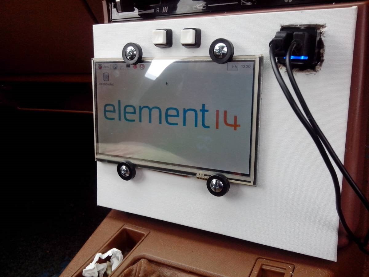
I used an unbranded 7" LCD screen and HDMI adapter board as the monitor for the Raspberry Pi. These are very cheap, but also inconsistent in quality. Some are able to run on the 5 volts from a USB port, while others need a higher voltage - even between identical looking models. They are also prone to having flaws on the LCD, like dead or stuck pixels, and often have poor viewing angles. Hopefully when the long rumoured official Raspberry Pi touch screen is released these problems will be a thing of the past, but for now it is a case of buyer beware.

The full completed circuit
If your cars dashboard already has a screen built in it might be usable for this project. The Raspberry Pi can output a composite A/V signal, just like what every DVD player and game console used long before HDMI was common. If you have an "Aux Video" or "AV input" option you'll just need a Raspberry Pi 3.5mm to 3 RCA cableRaspberry Pi 3.5mm to 3 RCA cable to wire it in. Keep in mind that the video quality of composite video is significantly inferior to HDMI, but there will be no change in quality of any video recorded by the camera board. It'll be hard to read text, so the Raspberry Pi will most likely have to be set up on a HDMI monitor first.
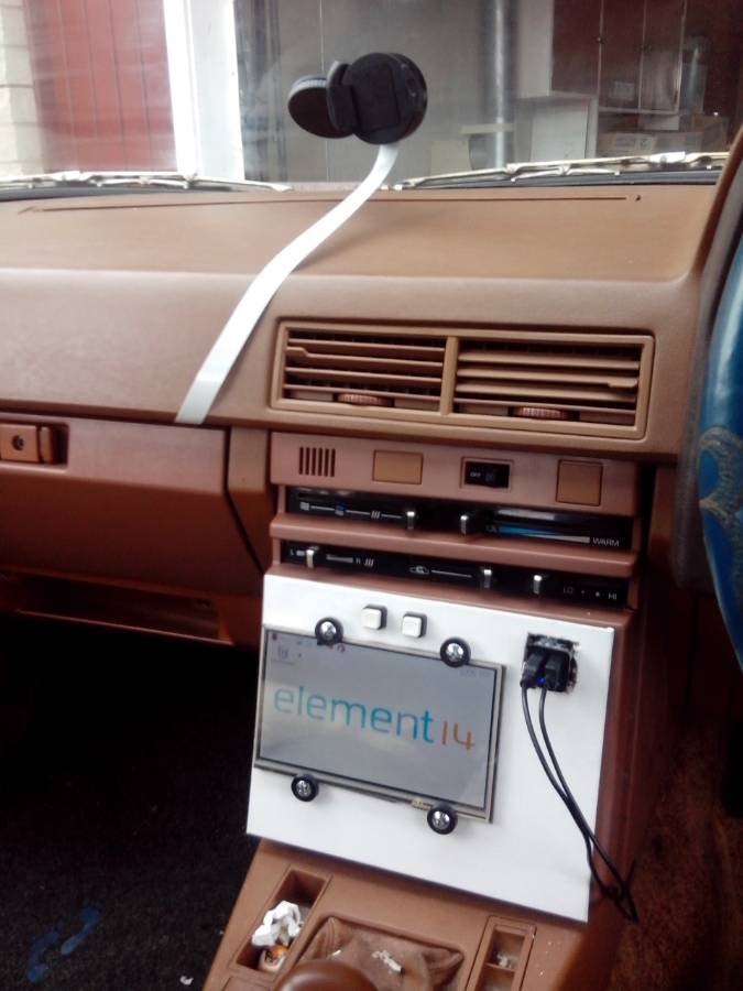
Unfortunately the dash in my 1983 Toyota didn't have a great spot to put a screen. To hold it in place I used rubber washers attached to small bolts along with double sided mounting tape attached to a piece of thick, solid card. I put the latching buttons in the card, using a spade bit on a drill to get the right sized holes. Strong cable ties attached the card to my cars centre console. I left the USB power adapter exposed and ran the cables back just to allow all the wiring to be easily removed if necessary.
I attached the Raspberry Pi to a sheet of card and placed it securely in the glove compartment. In order for the camera to mount on the windshield I had to use a longer ribbon cable, one meter as opposed to the standard 15 centimetres. You have to be careful when doing this. Because the cable is unshielded, having a longer run can cause problems with the video signal and even make it not work at all depending on the level of interference.
A USB car charger is an easy way to get the voltage to the right level for a Raspberry Pi. It also useful as most units you buy have a fuse built in, giving extra protection if your cars electrics may not be that reliable. Be sure to use a good quality charger that gives out a constant, smooth voltage. My Pro-Power AC adapterPro-Power AC adapter has two USB ports, I used one for the Raspberry Pi and the other for the LCD screen.
To get the button to activate the camera recording I used this Python script.
import datetime
import picamera
import RPi.GPIO as GPIO
GPIO.setmode(GPIO.BCM)
GPIO.setup(24, GPIO.IN, pull_up_down = GPIO.PUD_UP)

while True:
GPIO.wait_for_edge(24, GPIO.FALLING)
        dvrname = datetime.datetime.now().strftime("%y%m%d_%H%M%S")
        with picamera.PiCamera() as camera:
camera.resolution = (1920, 1080)
camera.start_preview()
camera.start_recording('/home/pi/' + dvrname + '.h264')
GPIO.wait_for_edge(24, GPIO.RISING)
camera.stop_recording()
GPIO.cleanup()
From the top down:
- Line 1, 2 and 3 import modules for controlling the camera board, accessing the GPIO interface and for reading the date and time respectively.
- Line 4 selects what numbering system is used to identify GPIO pins - I used the BCM numbering, the alternative is to use Board numbering. Be sure to double check what system you used when attaching the buttons to the Raspberry Pi.
- Line 5 sets the pin used to be 'up' or 'down'. This line allows buttons to be used with the GPIO without having to wire resistors. Setting it to up means one side of the button should be attached to a ground pin to bring it down.
- Line 6 sets up a while loop that will check if a certain condition is met before proceeding.
- Line 7 detects when out chosen GPIO pin is Falling - going from being up to down, or more simply when the attached button is pressed.
- Line 8 builds a filename for our recorded video, based on the current date and time for unique file names for every video and for easy sorting of videos.
- Line 9 is when we start using the camera.
- Line 10 sets the resolution to 1920x1080, also called Full HD.
- Line 11 starts the preview, letting the video from the camera be displayed live on screen. Remove this line if you don't want to see what is being recorded.
- Line 12 starts the recording and outputs it to the filename that was made in line 8.
- Line 13 detects when the GPIO pin is pulled up, or when the button is switched off.
- Line 14 stops the recording.
- Finally, line 15 cleans up our used GPIO pins to prevent clashes or things getting out of hand.
I then saved this python script as 'camera.py' in the /home/pi/ directory.
In order to have this script running in the background while Raspbian is running, the file at /etc/rc.local needs to be edited. Open it up and add the following line to the very bottom.
python /home/pi/camera.py &
The ampersand and the end is important, it ensures the script is always running in the background and will not close.
This script is fairly reusable, you could substitute the camera function for other code to get a Raspberry Pi to do all kinds of things on the flick of a switch. You can also do more things with the camera, like adjusting for low light or recording in slow motion. Look through the picamera documentation for all the extra details.
Using a Raspberry Pi as the core of a car DVR system has a big advantage. Rather than having to take the SD card out of the car to review the video footage, adding a WiPi wireless adapterWiPi wireless adapter lets you copy the videos from the Pi wirelessly. In Raspbian, set the directory where the cameras video files are saved as a network share. Then setup the WiPi to connect to your home WiFi network. Now as long as your car is in range of your wireless access point you can copy the video files remotely to your computer or tablet.
A few final things:
- Its a good idea to wire in switches to the power going into everything, just to be able to keep everything turned off. It will also let you turn the Raspberry Pi on again after shutting it down without having to unplug it.
- If wiring the system using the feed directly from your car battery you can run the risk of getting a flat battery if you forget to shut everything down. I used the ignition power feed to ensure that the key has to be in the car for it to get power. You can also set a shutdown timer in Raspbian that will turn everything off after being idle for a set period.
- You can run out of SD card storage space very fast recording full HD video. Try setting a lower frame rate to save space over the default 30 frames per second, or connect a USB flash drive and use that to record to.
- After the installation you have a full Raspberry Pi installed in your car! If you disable the video preview you can do whatever you want while recording, the quad core processor in the Raspberry Pi 2 makes this multitasking work well. Try installing media players and connect the audio output to your stereo, or doing other fun things. Great for entertainment when waiting for people in your car! Just please don't try and watch a movie while driving. If that's not illegal where you are, it probably should be.
If you have any questions or suggestions, leave them on the comments below or you can contact me on Twitter - @aaronights.
Top Comments