element14 Community
element14 Community
    Register Log In
  • Site
  • Search
  • Log In Register
  • Community Hub
    Community Hub
    • What's New on element14
    • Feedback and Support
    • Benefits of Membership
    • Personal Blogs
    • Members Area
    • Achievement Levels
  • Learn
    Learn
    • Ask an Expert
    • eBooks
    • element14 presents
    • Learning Center
    • Tech Spotlight
    • STEM Academy
    • Webinars, Training and Events
    • Learning Groups
  • Technologies
    Technologies
    • 3D Printing
    • FPGA
    • Industrial Automation
    • Internet of Things
    • Power & Energy
    • Sensors
    • Technology Groups
  • Challenges & Projects
    Challenges & Projects
    • Design Challenges
    • element14 presents Projects
    • Project14
    • Arduino Projects
    • Raspberry Pi Projects
    • Project Groups
  • Products
    Products
    • Arduino
    • Avnet Boards Community
    • Dev Tools
    • Manufacturers
    • Multicomp Pro
    • Product Groups
    • Raspberry Pi
    • RoadTests & Reviews
  • About Us
  • Store
    Store
    • Visit Your Store
    • Choose another store...
      • Europe
      •  Austria (German)
      •  Belgium (Dutch, French)
      •  Bulgaria (Bulgarian)
      •  Czech Republic (Czech)
      •  Denmark (Danish)
      •  Estonia (Estonian)
      •  Finland (Finnish)
      •  France (French)
      •  Germany (German)
      •  Hungary (Hungarian)
      •  Ireland
      •  Israel
      •  Italy (Italian)
      •  Latvia (Latvian)
      •  
      •  Lithuania (Lithuanian)
      •  Netherlands (Dutch)
      •  Norway (Norwegian)
      •  Poland (Polish)
      •  Portugal (Portuguese)
      •  Romania (Romanian)
      •  Russia (Russian)
      •  Slovakia (Slovak)
      •  Slovenia (Slovenian)
      •  Spain (Spanish)
      •  Sweden (Swedish)
      •  Switzerland(German, French)
      •  Turkey (Turkish)
      •  United Kingdom
      • Asia Pacific
      •  Australia
      •  China
      •  Hong Kong
      •  India
      •  Korea (Korean)
      •  Malaysia
      •  New Zealand
      •  Philippines
      •  Singapore
      •  Taiwan
      •  Thailand (Thai)
      • Americas
      •  Brazil (Portuguese)
      •  Canada
      •  Mexico (Spanish)
      •  United States
      Can't find the country/region you're looking for? Visit our export site or find a local distributor.
  • Translate
  • Profile
  • Settings
Raspberry Pi Projects
  • Products
  • Raspberry Pi
  • Raspberry Pi Projects
  • More
  • Cancel
Raspberry Pi Projects
Blog Data Acquisition Board for Pi Pico
  • Blog
  • Documents
  • Events
  • Polls
  • Members
  • Mentions
  • Sub-Groups
  • Tags
  • More
  • Cancel
  • New
Join Raspberry Pi Projects to participate - click to join for free!
  • Share
  • More
  • Cancel
Group Actions
  • Group RSS
  • More
  • Cancel
Engagement
  • Author Author: shabaz
  • Date Created: 3 Nov 2023 11:24 PM Date Created
  • Views 5121 views
  • Likes 15 likes
  • Comments 68 comments
  • rpiintermediate
  • ADC (Analog-to-Digital Converter)
  • pico
  • data acquisition
  • ads1115
  • rp2040
  • daq
  • raspberry_pi_projects
  • adc
  • test&measurement
  • pi pico
Related
Recommended

Data Acquisition Board for Pi Pico

shabaz
shabaz
3 Nov 2023
Data Acquisition Board for Pi Pico

Table of Contents

  • Introduction
  • Circuit Diagram
  • Board Assembly
  • Testing It
  • Known Issues
  • Next Steps


Introduction

Data acquisition is pretty essential! However, it proved surprisingly difficult to find a plug-on analog-to-digital (ADC) board for the Pi Pico. It was time to create a custom board!

This project is a work in progress. Some of the functionality has been implemented, but things may still need to be tweaked.

The board described here supports high-res 16-bit measurements for inputs in the range +/- 4V (the range can be modified), and it has two channels (you could stack boards for more channels).

Even if you're not interested in analog data acquisition, perhaps bits of this project are helpful if you're interested in working with ambient temperature sensors and non-volatile memory (EEPROM).

image

Circuit Diagram

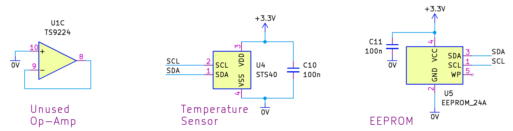
The core circuit for the ADC board is shown below. The two inputs labeled AIN_1 and AIN_2 are amplified by two op-amps from a 4-in-one op-amp chip. Another op-amp from that chip is used to create a mid-rail supply, which is needed to bias the op-amp input since everything runs from single-ended supplies. The last op-amp in the chip is unused.

Note that AIN_2 has a corresponding AIN_2’ pin, which, optionally, can be useful for connecting directly to the 0V end of a low-side current sense resistor if desired. The gain of the op-amp would most likely need to be changed if it is used for current measurement.

image

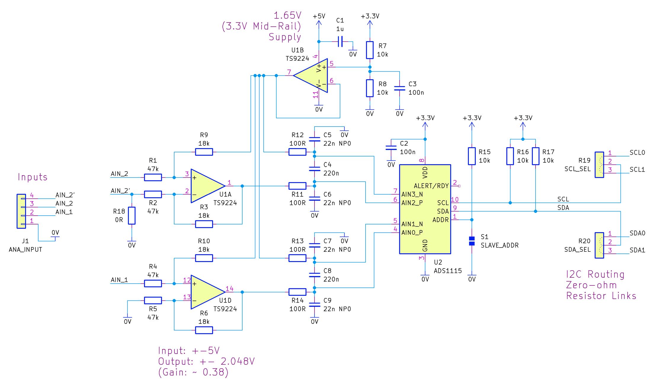
The ADC chip ADS1115 can have up to 4 channels, but since we use it in a differential input mode, only two channels are available per board. More boards could be used if more than two channels are needed for a project.

The input range for the components on the board are +-4V (although the input does extend to +5V). The reason for this is that originally the components were sized for a larger range, which only works if the ADC chip could operate from 5V, but that's not possible because it interfaces to a Pi Pico with 3.3V levels (the ADC I2C input thresholds are not compatible with such operation). So, consider the input range to be +-4V, and if you desire a different range then you could scale that with either a potential divider or an amplifier on the input, or by changing resistors on the board.

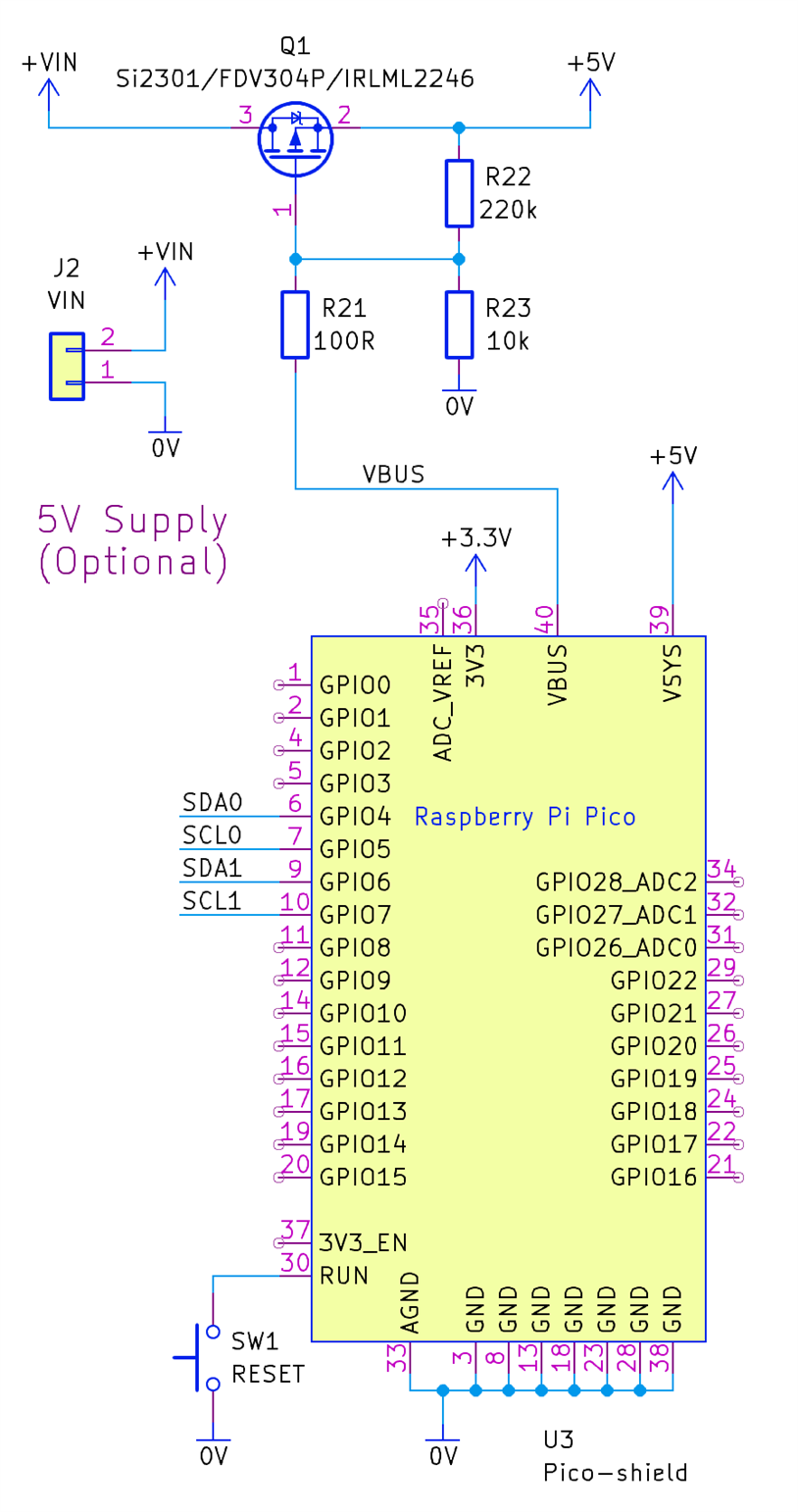
The connections to the Pi Pico are shown in the circuit diagram below. The only GPIO pins that are used are SDA and SCL, and with wire links those pins can be GPIO4+5, or GPIO6+7, to reduce the chance of clashes with other existing hardware that may also be connected to the Pico.

A MOSFET is used so that the supply for the Pico and ADC board can come from either the Pico’s USB socket, or from an external 5V source connected to +VIN.

image

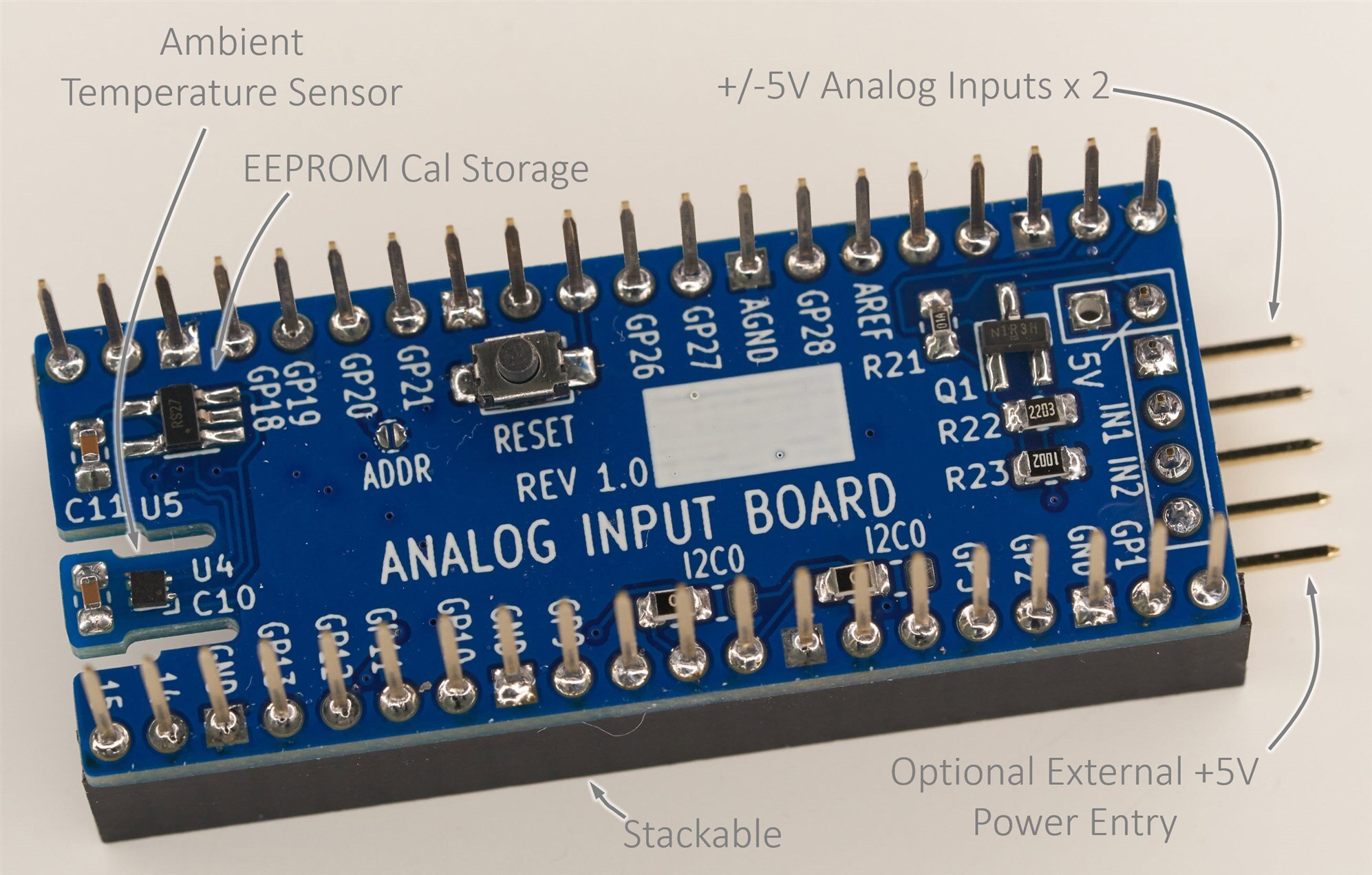
Finally, a temperature sensor and an EEPROM are also present on the board if required. It would be nice to use an EEPROM with address pins so that more than one board could be attached in the future (today, if more than one board is used, then the EEPROM should only be soldered on one board). Also, it could make sense to power the temperature sensor from a GPIO pin in the future, but for now, it is permanently powered by 3.3V from the Pico.
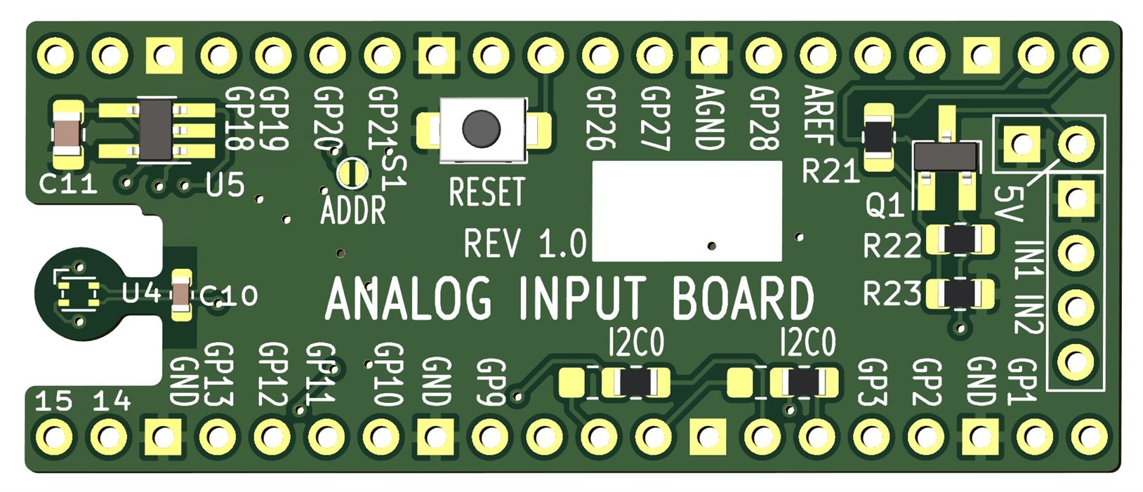
image

Board Assembly

The diagrams below can be used to aid in assembly.

image

Everything is feasible to hand-solder with a soldering iron or with a hot air tool. The integrated circuit (IC) footprints were specifically designed to make it easy to solder with basic tools.

image


The temperature sensor on the underside of the board is tiny but still hand-solderable. The info is here: Soldering Tiny Temperature Sensors  

image

Note that there is a bodge fix on the Rev 1 board. R7 is wrongly connected to the 5V rail when it should be connected to 3.3V. The fix is to mount R7 on just one pad and then connect the other end of the resistor to 3.3V using a short wire. I achieved it by passing the wire through a spare hole.

image

Testing It

There is a test program on GitHub (feel free to contribute to the code if you can [even if it is just suggestions]. Thanks Jan Cumps for some work already done to it). When run, it should repeatedly display the voltage measurements for the two channels plus the board temperature. It seems reasonably accurate, but not many measurements have been done so far. This is still a new project!

The test program is a playground for trying out functionality related to the board. It also provides access to the EEPROM for configuration. To gain access, pull GPIO21 or GPIO27 (either is fine) low on power-up. When that is done, a configuration menu will appear on the serial console.

image

Known Issues

1. Resistor R7 is wrongly connected to 5V. It needs to be wired to 3.3V instead.

2. The input range is not precisely +/-5V. It is approximately -4.2V to 5.3V, i.e. it’s not possible to measure down to –5V currently. Hopefully, this can be improved with resistor value modifications.

3. The temperature sensor isn’t currently practical for ambient readings. The measured temperature is several degrees higher. The next board revision will try to improve that. The board will look something like what is shown in the render below (this is not completed yet).

4. If more than one board is attached, then the temperature sensor and EEPROM chips need to be only on one board.

image

Next Steps

A new revision board will be created at some point to address the issues. If you spot any problems or have suggestions for the hardware or the software, please let me know! Probably, the next revision board cannot accommodate too many changes since it is almost complete, but I won’t order a second board for now while this first board is still fresh.

If you wish to build the revision 1 board, the Gerber files are attached. I’ll upload the KiCad files to a GitHub repo at some point (they are currently being worked on for the next revision). The source code is on Github, but as mentioned, it is just test code for now, not very pretty.

If you have any ideas for the project, or example applications, it would be great to hear about them.

Thanks for reading!

pico_adc_basic_gerbers_rev1.zip

pico-shield-symbol-and-footprint-rev1-kicad-7.zip

  • Sign in to reply

Top Comments

  • shabaz
    shabaz over 1 year ago in reply to ggabe +1
    Interesting device! I too think a SCPI controlled system with 3.5 or so digits and several ranges to make use of that is good enough for lots of serious work. Might be worth allocating GPIO and designing…
  • Jan Cumps
    Jan Cumps over 1 year ago in reply to wolfgangfriedrich

    Here are comparisons, based on the same dataset of 100 samples. Taken at 860 samples / second. I didn't use rolling averaging, but each time averaged a bucket  (10, 20, 50 and 100 samples).

    Voltage source: 2.5 V DC reference

    Average done in firmware, over all 860 raw sample data, then converted to volt: 2.5120437 V

    image

    spreadsheet attached:

    averaging.zip

    • Cancel
    • Vote Up 0 Vote Down
    • Sign in to reply
    • More
    • Cancel
  • Jan Cumps
    Jan Cumps over 1 year ago in reply to wolfgangfriedrich

    Taken at a different time. Tomorrow I can take a set of 860, and show all tree based on the same samples.

    • Cancel
    • Vote Up 0 Vote Down
    • Sign in to reply
    • More
    • Cancel
  • wolfgangfriedrich
    wolfgangfriedrich over 1 year ago in reply to Jan Cumps

    Interesting. Any explanation why the 215 average is all above the single measurements. One would expect the 215 between the min-max of the single, similar to the 860. 

    • Cancel
    • Vote Up 0 Vote Down
    • Sign in to reply
    • More
    • Cancel
  • Jan Cumps
    Jan Cumps over 1 year ago

    Some sample results, using bulk sampling and averaging

    • 10 single measurements; taken in bulk in 1/86 sec
    • averaging 215 samples, taken in bulk in 1/4 sec
    • averaging 860 samples, taken in bulk in 1 sec

    image

    All samples in the exercise are taken at the same speed, 860 samples per second. On the yellow line, each data point is one sample. On the red line it represents an average of 215 samples. On the blue line, 860 samples are averaged for each data point.

    I think that I have a wrong value in the spreadsheet for the first 215-avg data point. Ignore that.

    • Cancel
    • Vote Up 0 Vote Down
    • Sign in to reply
    • More
    • Cancel
  • Jan Cumps
    Jan Cumps over 1 year ago

    Modding time: I connected the ADS1115 READY pin to a GPIO (GP13). To support continuous mode.

    image 

    I plan to launch an i2c read at each pulse.

    image

    Also late late change request for a future version: a little pad connected to pin 2 would make it easier, for modifications, to get at the ADC's pin 2: ALERT/RDY.
    It's doable to tag a tiny wire directly to the IC leg, but it's somewhat fiddly.

    • Cancel
    • Vote Up 0 Vote Down
    • Sign in to reply
    • More
    • Cancel
>
element14 Community

element14 is the first online community specifically for engineers. Connect with your peers and get expert answers to your questions.

  • Members
  • Learn
  • Technologies
  • Challenges & Projects
  • Products
  • Store
  • About Us
  • Feedback & Support
  • FAQs
  • Terms of Use
  • Privacy Policy
  • Legal and Copyright Notices
  • Sitemap
  • Cookies

An Avnet Company © 2025 Premier Farnell Limited. All Rights Reserved.

Premier Farnell Ltd, registered in England and Wales (no 00876412), registered office: Farnell House, Forge Lane, Leeds LS12 2NE.

ICP 备案号 10220084.

Follow element14

  • X
  • Facebook
  • linkedin
  • YouTube