


Welcome to installment #005 of Project: Foginator 2000, part of the 2015 Raspberry Pi Halloween Project series here at Element14. In this week's episode I am going to demonstrate how to get Neopixel (WS2812B) LED modules working with the Raspberry Pi 2. Unfortunately as you will see, this is an almost impossible task as the previously working library is only compatible with Raspberry Pi versions up to the Model B+.
Below is a table containing the parts you will need for this segment of the project. In addition to these parts you will need to connect the Raspberry Pi to the internet either via a wifi dongle, or a wired Ethernet connection. You will also need three colors of stranded hook-up wire, a soldering station, solder, and some 0.100 male header pins.
Newark Part No. | Notes | Qty | Manufacturer / Description |
38Y646738Y6467 | RPi | 1 | RASPBERRY PI 2, MODEL B |
38Y647038Y6470 | SD Card | 1 | RASPBERRY PI 8GB NOOBS MICRO SD CARD |
44W493244W4932 | PSU | 1 | USB PORT POWER SUPPLY 5V, 1A |
06W104906W1049 | USB Cable | 1 | USB A PLUG TO MICRO USB B PLUG |
53W628553W6285 | WiFi Dongle | 1 | USB WIFI MODULE |
26Y845826Y8458 | Fog Coloring Rings | 1 | NEOPIXEL RING - 16 X WS2812 |
26Y846026Y8460 | Mood LEDs | 1 | NEOPIXEL DIGITAL RGB 1M 144LED BLACK |
34C109234C1092 | PSU Vreg | 1 | LM7805 LINEAR VOLTAGE REGULATOR, 5V, TO-220-3 |
58K379658K3796 | PSU LED Resistor | 1 | METAL FILM RESISTOR, 1KOHM, 250mW, 1% |
17F216517F2165 | PSU Filter Cap | 1 | CERAMIC CAPACITOR 0.1UF, 50V, X7R, 20% |
69K794969K7949 | PSU Filter Cap | 1 | ELECTROLYTIC CAPACITOR 47UF, 50V, 20% |
69K790769K7907 | PSU Filter Cap | 1 | ELECTROLYTIC CAPACITOR 100UF, 50V, 20% |
14N941814N9418 | PSU LED | 1 | LED, RED, T-1 3/4 (5MM), 2.8MCD, 650NM |
| 49Y756949Y7569 | RPi Sense Hat | 1 | Raspberry Pi Sense HAT |
| 13T927513T9275 | Arduino Nano | 1 | Arduino Nano V3 |
| 38K032838K0328 | 10k Resistor | 1 | Multicomp 10k Resistor |
The Theory

Neopixel’s are the brand name for the popular WS2812B individually addressable RGB LED modules, and are marketed and sold by Adafruit here at Element14. You can find WS2812B strips, rings, sticks, and individual modules on various electronic retail outlets as well, but for the purpose of this project, I will be using genuine Neopixel strips and rings from Adafruit.
The NeoPixel line is the latest advance in the quest for a simple, scalable and affordable full-color LED. Red, green and blue LEDs are integrated alongside a driver chip into a tiny surface-mount package controlled through a single wire. They can be used individually, chained into longer strings or assembled into still more interesting form-factors.
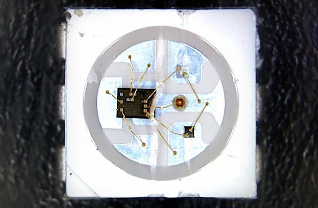
As you can see, each Neopixel contains a small microcontroller built into each LED module, with control wires emanating to each LED die. Neopixels use a single-wire protocol making them easy to integrate into any project without consuming valuable GPIO resources. Neopixels pass data along to the next module in-line, and can be individually controlled in single module,strip and matrix form factors.
Unfortunately, Neopixels require very strict timings, and this causes a lot of headache when attempting to control them from something like a Raspberry Pi, as it’s GPIO pins are software based, and not hardware based like those of an Arduino. Raspberry Pi models up to the B+ were able to skirt around this limitation thanks to the excellent rpi_ws281x library created by Jeremy Garff, but as I recently found out, the library does not seem to function on the new Raspberry Pi 2 boards.
I spent a good portion of last week looking for a solution to this problem, and to be honest, I came up with nothing. This caused me to freak out a little bit, and Neopixels play a very large role in this project. After much deliberation, and consultation with some friends here at Element14, I decided to abandon my quest to get Neopixels working with the Raspberry Pi 2. Instead of directly controlling them with the Pi, I decided to go a much easier route, by controlling them with an Arduino Nano, which will be triggered by the Raspberry Pi.
As many of you may already know, Adafruit has an excellent guide to getting Neopixels up and running on an Arduino, and even wrote their own library. (Albeit it is a modified version of the pre-existing fastLED library.) To keep things simple and easy to understand for those of you following along at home, I stuck with the Adafruit Neopixel Library despite being more familiar with the fastLED library. If you are looking for more code examples for driving WS2812B modules, give fastLED a try.

As I briefly mentioned earlier, Neopixels utilize a single-wire data format, meaning they only require a single data wire regardless if your strip has one module or one thousand modules. The only other connections required are 5V and GND connections. It is very important to remember that with each “pixel” you get three LEDs that are being driven. This means that Neopixel strips, and rings can draw a large amount of current. I find that on a standard Arduino board, only about 60 Neopixels can be driven before browning out the board, and that number diminishes by half, if the strip is set to display white at full brightness.
For this reason, I recommend driving your Neopixels with a separate power source such as a 5V 1A regulated source, or a 5V 2A wall transformer. You can also power the strip with a 4x AA battery box. Adafruit also recommends filtering the power input with a large capacitor, and limiting the current on the data line with a resistor. I find that this is usually not needed, but it will prevent a pixel from dying in the event you accidentally plug the strip in while the system is powered up.
Wiring the Neopixels, Arduino Nano, and Raspberry Pi
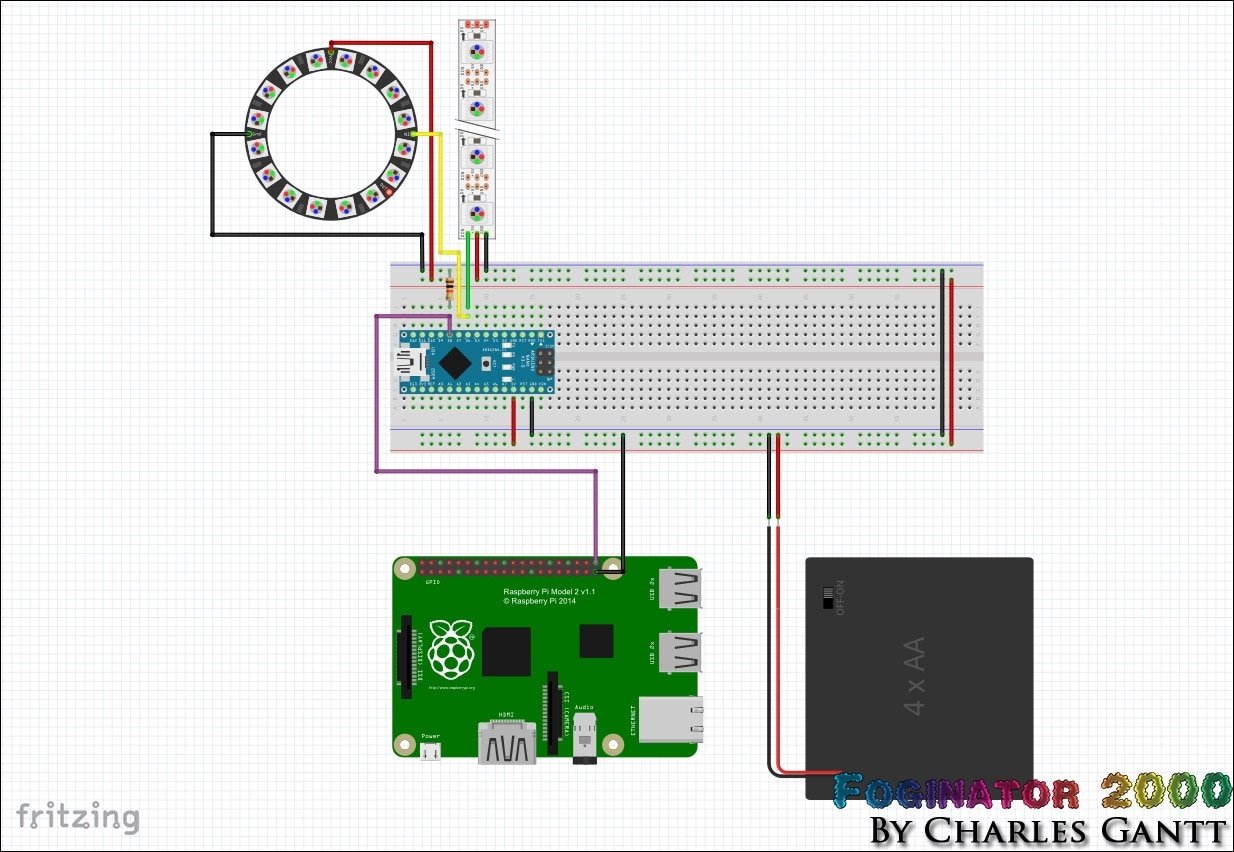
Wiring up the Neopixels to the Arduino is fairly straightforward,and is as simple as following the diagram above. Note that I have connected the data-in line from both the Neopixel Ring and the Neopixel strip to the Arduino Nano’s digital pin 6. This allows me to drive both Neopixel devices with the same code. Also note that I have connected a 4X AA battery pack in the image for illustration purposes. As you will see later, I am using an LM805 VReg-based power supply in the physical application.
Connecting the Raspberry Pi to the Arduino is simple as well. Connect the Raspberry Pi’s GPIO Pin 21 to the Arduino Nano’s Digital Pin 8. Then connect one of the Raspberry Pi’s GND pins to the shared GND circuit between the Neopixels and Arduino Nano. It is very important that all of the ground’s in this circuit are connected together. Finally, a 10k Ohm resistor needs to be connected as a pulldown resistor on the Arduino’s Digital Pin 8. This will prevent any false triggers from happening.
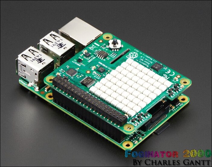
Since we are using the Raspberry Pi Sense Hat with our Raspberry Pi, we need to make some slight modifications to the Sense Hat before we can connect any jumper wires to the GPIO headers. As you can see in the image above, the header pins that come with the sense hat do not protrude past the black plastic bar on top of the sense hat.
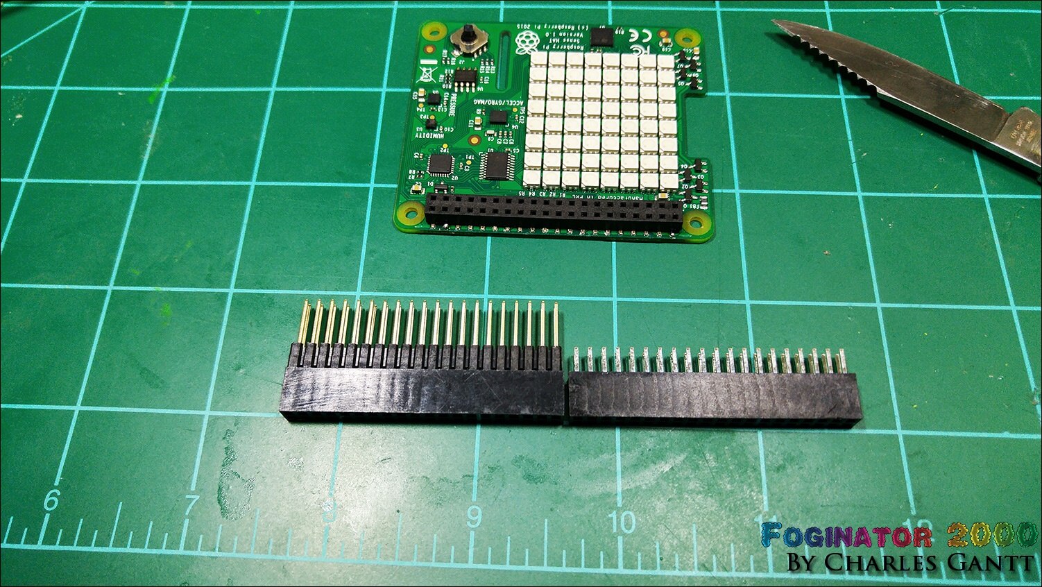
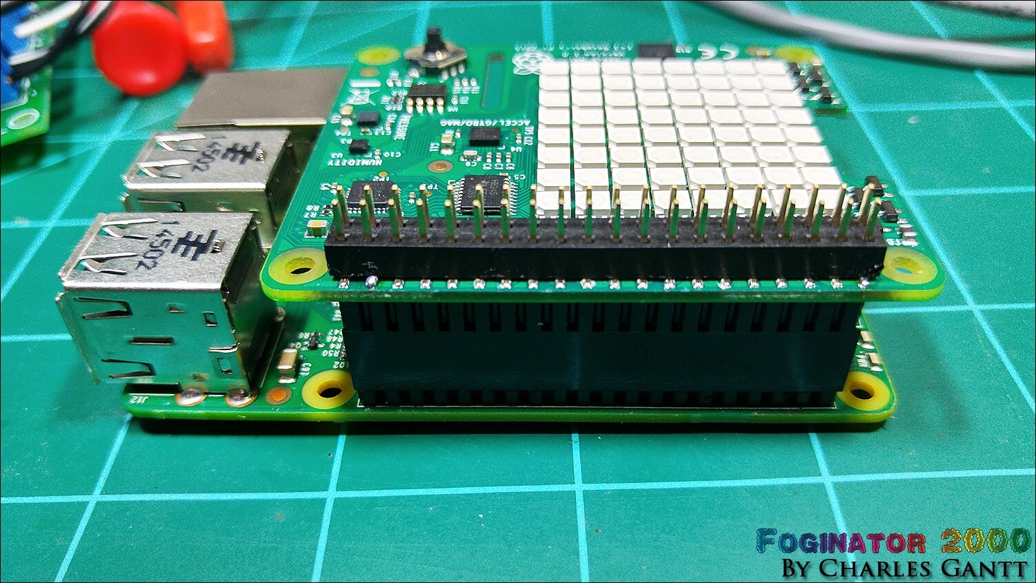
Unfortunately figuring out how to get around this issue is not something that has been widely discussed anywhere on the internet. However, I did manage to find a post on the Astro Pi forums that mentioned buying some extra-long header pins from Adafruit. This is one of the reasons this post has been delayed for so long. As you can see in the image above, the extra-long pins from Adafruit are about 5mm longer than the ones that ship with the Sense Hat.
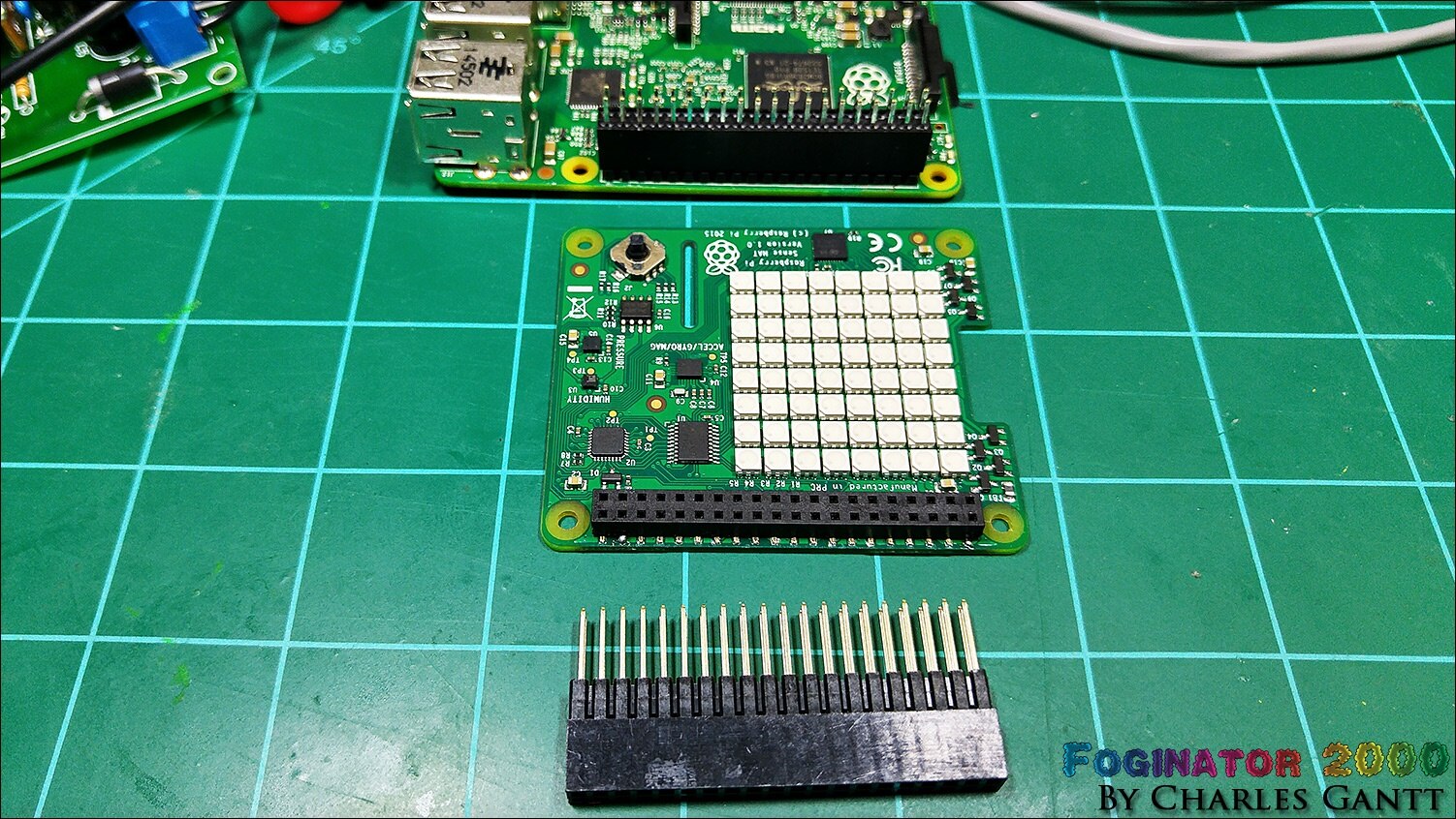
The first step in installing the new header pins is to gently pry the Sense Hat off of its existing header pins. The Sense Hat was designed with this in mind, and prying the existing header pin strip out is easy when done slowly and carefully with a small flat-blade screw driver. Once removed, you can simply slide the longer header pins into place.
Now you are ready to hook up everything as per the instructions above. In the image below you can see how I have everything laid out. Note that for this portion of the project to work, you need to have followed all of the previous installment’s instructions as well.
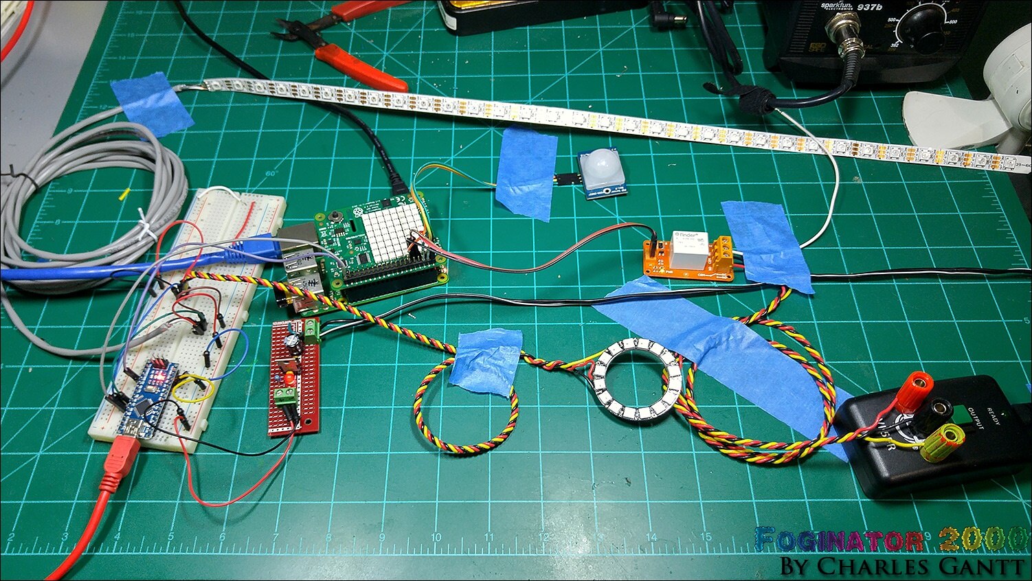
It looks like a bit of a mess, but with everything laid out and taped down, I could easily troubleshoot any issues that arose.
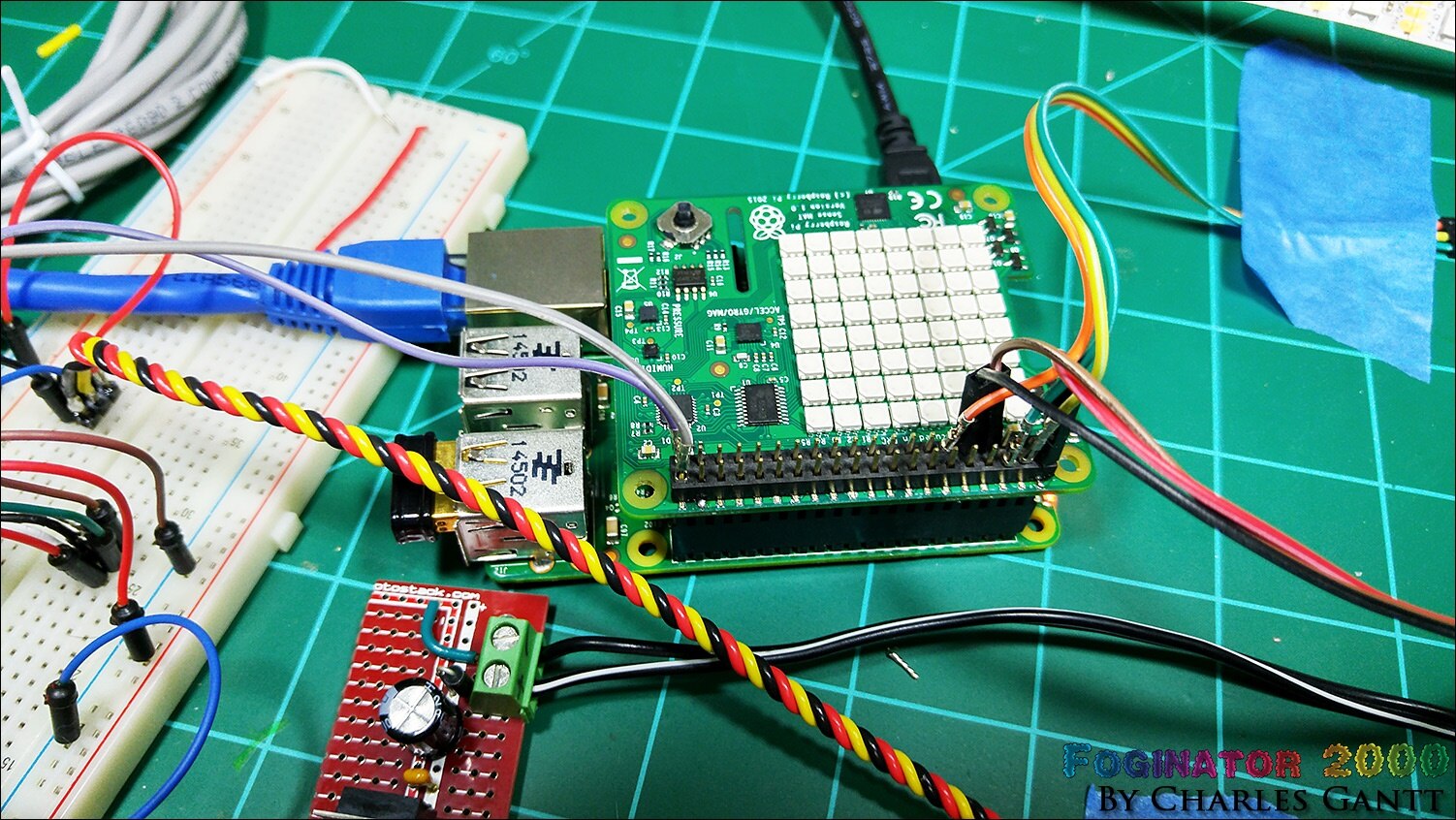
Here you can see the connections made to the Raspberry Pi. Note that I have removed some of the plastic connectors from some of the jumper wires. The header pins only stick about 5mm above the surface of the black plastic bar, and some of my jumpers were having issues keeping a secure connection.
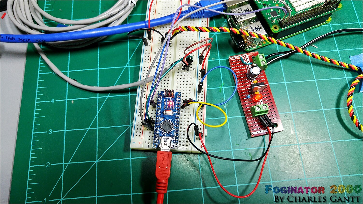
Here is a shot of how I have the Arduino Nano connected to the breadboard and wired up. Note that the grey wire is connected to the neopixel strip, and the twisted yellow, red, and black wires are connected to the neopixel ring. In this image, you can also see the LM7805-based 5V power supply I built. More on that later.
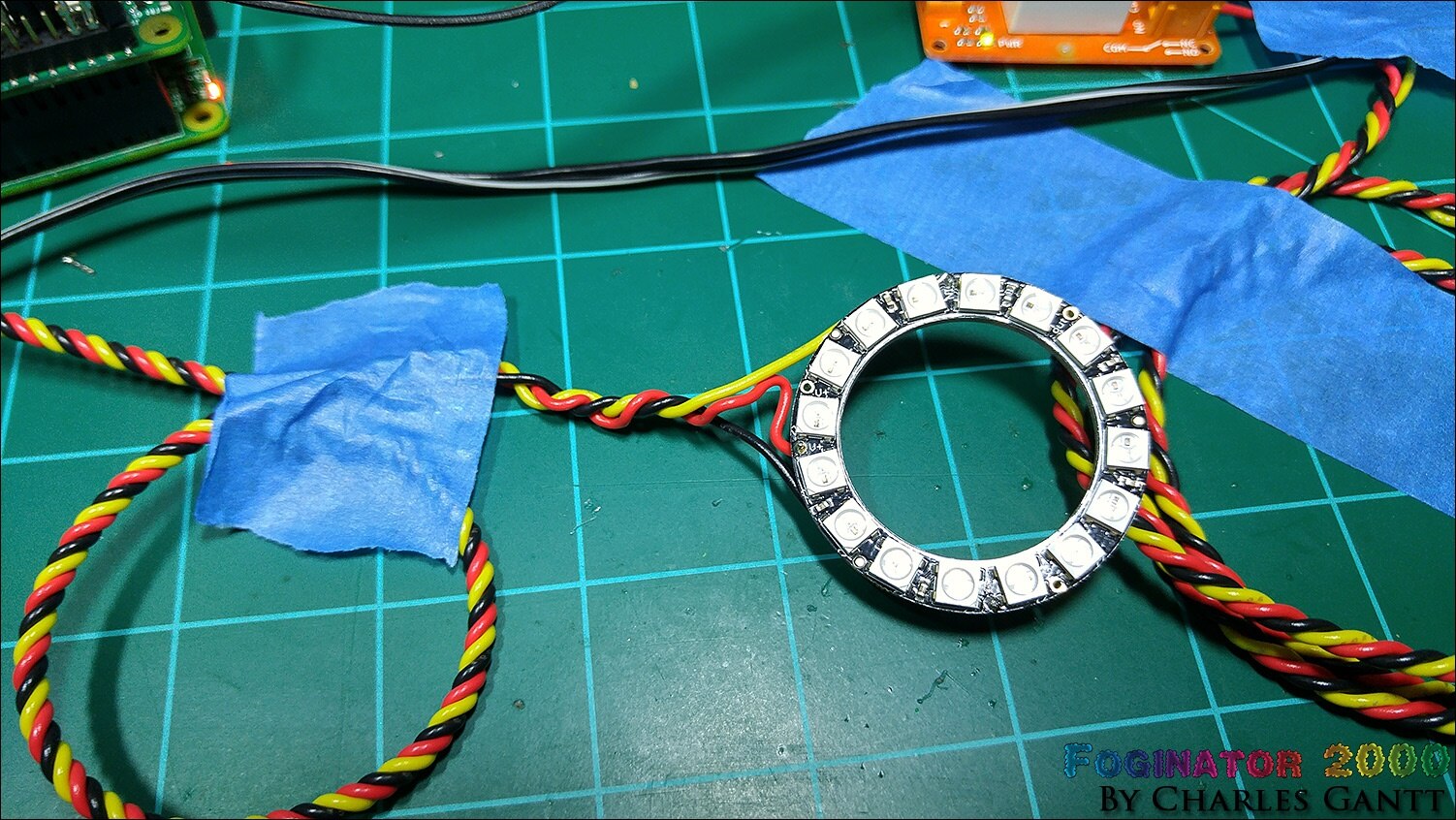
Finally, a shot of the NeoPixel ring wired up. Note that these rings do not come pre-wired, and you will need to solder wires to it.
Building a 5V Regulated Power Supply
This is the same PSU that I built for my Trick or Trivia Halloween Candy Dispenser #004 - Building The Candy Dispenser & Servo Coding project, so I have re-used its images below. To build this PSU you will need the following components, as well as a soldering iron, flush cutters, and a 12-30V DC power source.
58K382758K3827 | Resistors | 1 | METAL FILM RESISTOR, 220 OHM, 250mW, 1% |
10M846410M8464 | General Purpose Diode | 1 | 1N40011N4001 Rectifier Diode 50 V 1 A |
34C109234C1092 | PSU Vreg | 1 | 7805 LINEAR VOLTAGE REGULATOR, 5V, TO-220-3 |
17F216517F2165 | PSU Filter Cap | 1 | CERAMIC CAPACITOR 0.1UF, 50V, X7R, 20% |
69K790769K7907 | PSU Filter Cap | 1 | ELECTROLYTIC CAPACITOR 100UF, 50V, 20%, |
14N941814N9418 | PSU LED | 1 | RED, T-1 3/4 (5MM) |
| 49Y171249Y1712 | 7-Inch Touch Screen | 1 | Raspberry Pi 7" Touch Screen Display |
| 66H746266H7462 | Strip Board | 1 | VECTOR ELECTRONICS-8022-PCB, Tracks(Strip Board) |
| 21M490921M4909 | Screw Terminal | 2 | MOLEX-39543-0002-TERMINAL BLOCK |
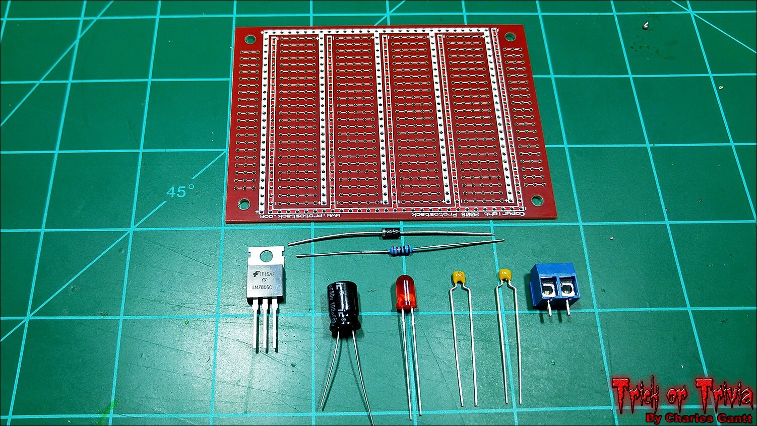
A 5V regulated power supply circuit is quite simple to build thanks to the fairly common LM7805 voltage regulator, and requires just five components to get up and running. A 100uF capacitor, two 0.1pF ceramic capacitors, a 1N004 diode, and the LM7805 regulator. I am adding two screw terminals, and an indicator LED to the mix. I want to design a pcb for this, but for now a piece of protoboard will work just fine.
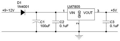
Following the schematic above, build the power supply and solder in each component. The protoboard I am using is different from the one listed above as I have a big supply of these from Protostack.com, so I just used one of mine.
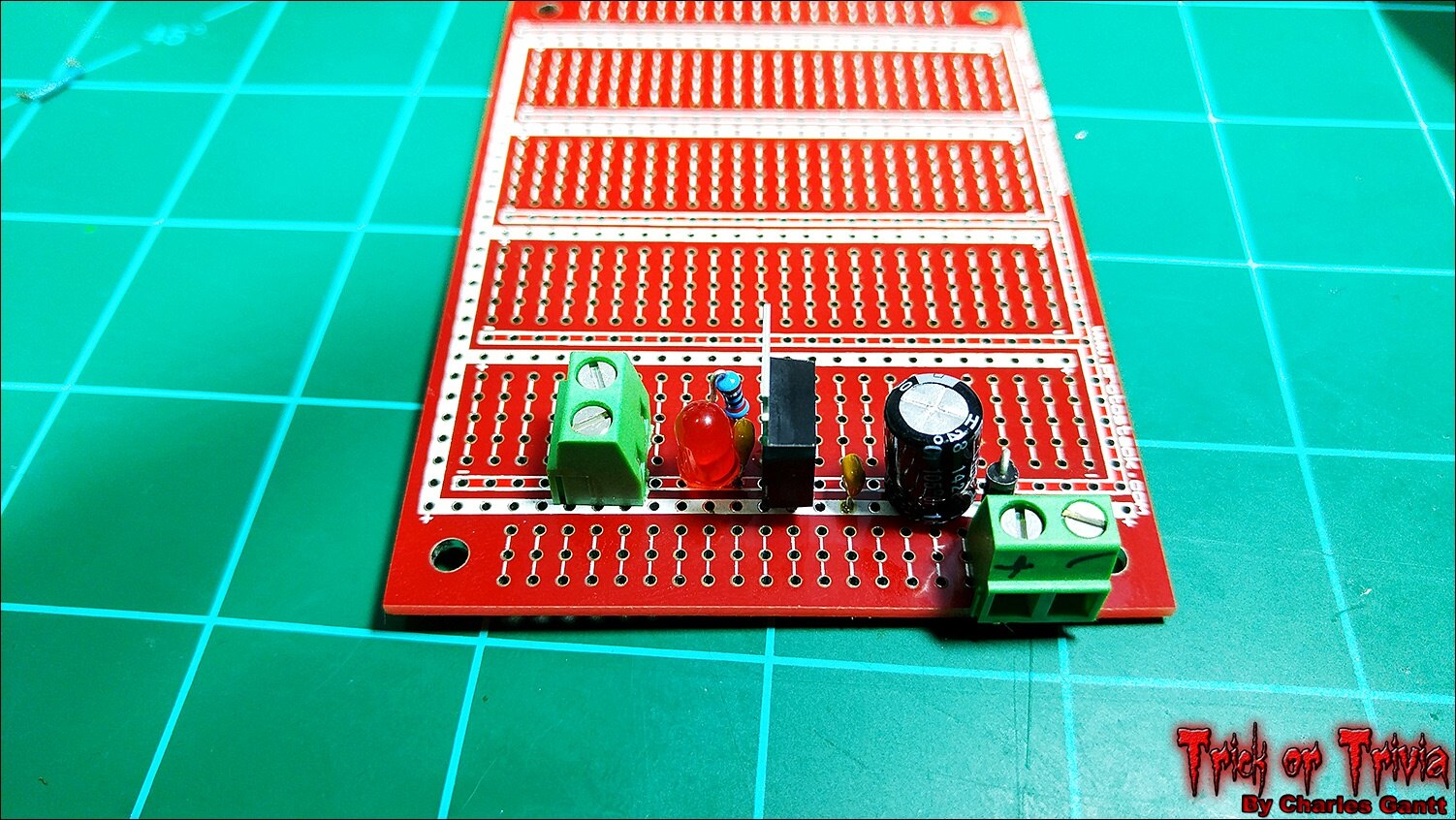
With all of the components soldered together, I made the necessary jumps from each component to the next. I lucked out with the Protostack board as it has integrated power and ground rails. This cut down on the number of jumps I needed to make.
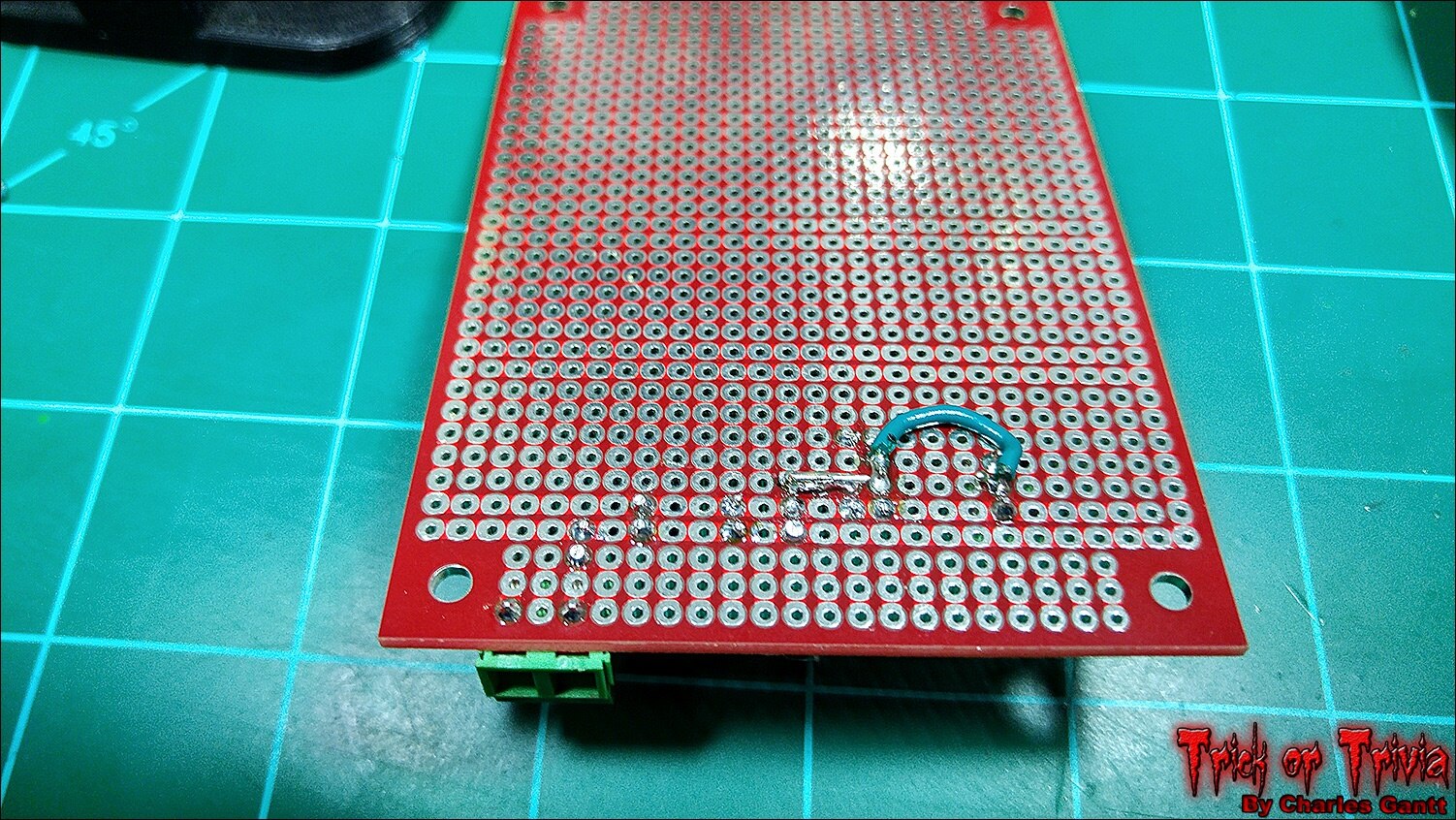
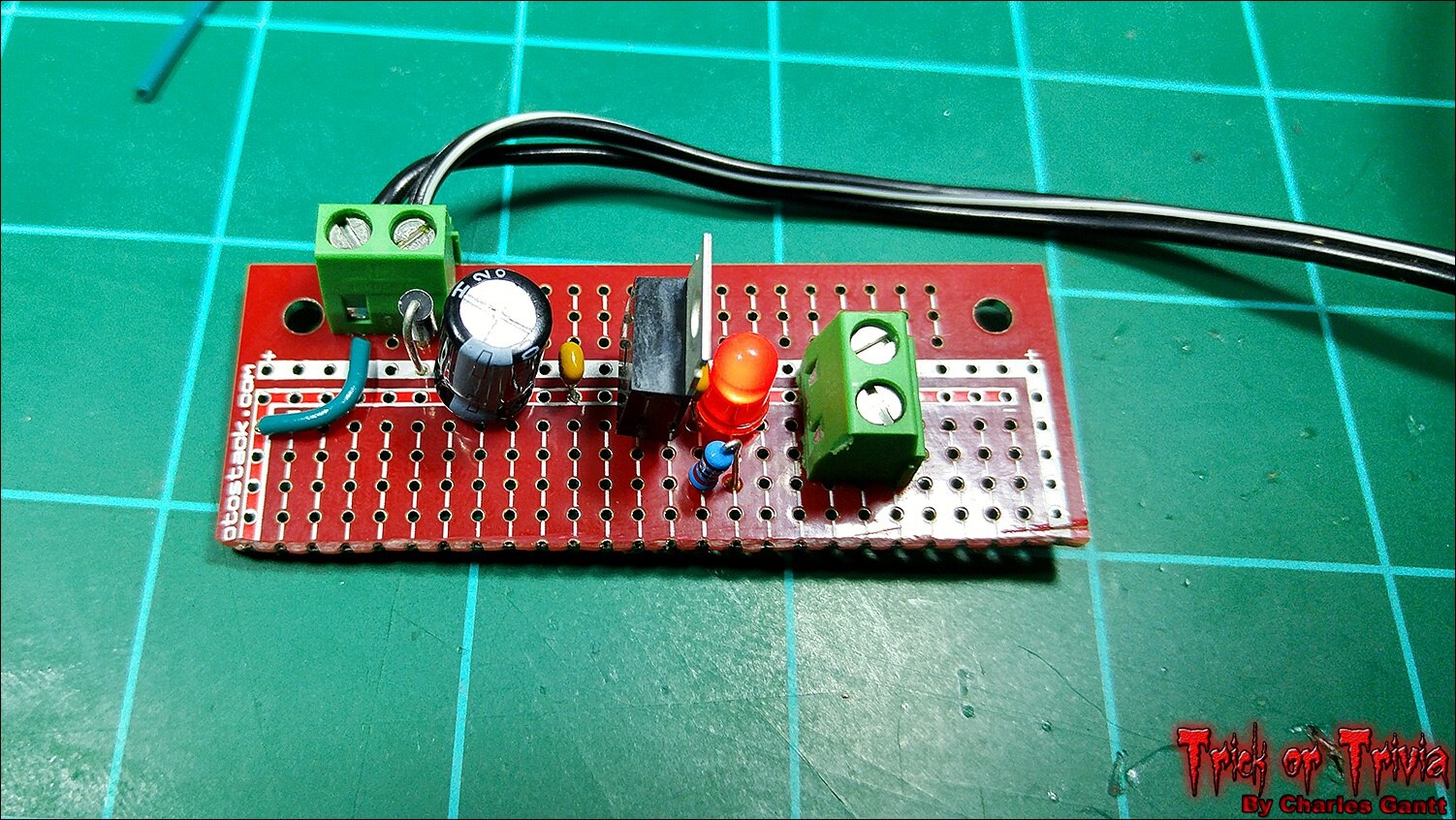
With everything soldered up, I trimmed the board down to reduce its size, and connected a 12v 1amp power source. The red LED lit up and I confirmed 5V out with a multimeter.
The Neopixel Code
With everything connected, load the Arduino IDE and make sure the Adafruit Neopixel Library is installed. Refer to Adafruit’s Neopixel Uber Guide if you need help installing the library. Additionally, I won’t be going over the Arduino sketch that will drive the Neopixels in great detail as Adafruit does a good job at that in the code’s comments.
To keep things simple, I am using a modified version of Adafruits Strand Test example. I have added some custom code that looks for a high signal on the Arduino Nano’s digital pin 8, and included an else statement that tells the neopixels to turn off if no high signal is present. As always, you can find all of the code used in the Foginator 2000 project at its Github Repository.
/* This code is adapted from the StrandTest example from Adafruit's Neopixel library. Please visit adafruit.com to download the neopixel library in order to use this code. https://learn.adafruit.com/adafruit-neopixel-uberguide/arduino-library */

#include <Adafruit_NeoPixel.h>

#define PIN 6

// Parameter 1 = number of pixels in strip
// Parameter 2 = Arduino pin number (most are valid)
// Parameter 3 = pixel type flags, add together as needed:
//  NEO_KHZ800  800 KHz bitstream (most NeoPixel products w/WS2812 LEDs)
//  NEO_KHZ400  400 KHz (classic 'v1' (not v2) FLORA pixels, WS2811 drivers)
//  NEO_GRB    Pixels are wired for GRB bitstream (most NeoPixel products)
//  NEO_RGB    Pixels are wired for RGB bitstream (v1 FLORA pixels, not v2)
Adafruit_NeoPixel strip = Adafruit_NeoPixel(60, PIN, NEO_GRB + NEO_KHZ800);

// IMPORTANT: To reduce NeoPixel burnout risk, add 1000 uF capacitor across
// pixel power leads, add 300 - 500 Ohm resistor on first pixel's data input
// and minimize distance between Arduino and first pixel.  Avoid connecting
// on a live circuit...if you must, connect GND first.

int rasPin = 8; // defines digital pin 8 as rasPin
int val = 0; // creates an integer called val, and assigns it a value of 0.

void setup() {
  strip.begin(); // Initialize the pixel strip
  strip.show(); // Initialize all pixels to 'off'
  pinMode(rasPin, INPUT); // sets rasPin to an Input pin
  }

void loop() {
val = digitalRead(rasPin); // tells the arduino to take a reading on rasPin and store the value in the val integer we declared earlier.

if (val == HIGH) // says if val is equal to 1, run the following code
{
  delay(1000); // wait one second
  rainbowCycle(30); // run the rainbowCycle function
  }
  else // tells the arduino that if val equals anything other than 1 (high) to run the following code.
  {
  colorWipe(strip.Color(0,0,0), 100); // sets each pixel to black (off) one by one via the colorWipe function
    }
}

// This function makes a rainbow equally distributed throughout the strip
void rainbowCycle(uint8_t wait) {
  uint16_t i, j;

  for(j=0; j<256*5; j++) { // 5 cycles of all colors on wheel
    for(i=0; i< strip.numPixels(); i++) {
      strip.setPixelColor(i, Wheel(((i * 256 / strip.numPixels()) + j) & 255));
    }
    strip.show();
    delay(wait);
  }
}

// This function fill the dots one after the other with a color
void colorWipe(uint32_t c, uint8_t wait) {
  for(uint16_t i=0; i<strip.numPixels(); i++) {
      strip.setPixelColor(i, c);
      strip.show();
      delay(wait);
  }
}

//This code generates a color-wheel value generator.
// Input a value 0 to 255 to get a color value.
// The colours are a transition r - g - b - back to r.
uint32_t Wheel(byte WheelPos) {
  if(WheelPos < 85) {
  return strip.Color(WheelPos * 3, 255 - WheelPos * 3, 0);
  } else if(WheelPos < 170) {
  WheelPos -= 85;
  return strip.Color(255 - WheelPos * 3, 0, WheelPos * 3);
  } else {
  WheelPos -= 170;
  return strip.Color(0, WheelPos * 3, 255 - WheelPos * 3);
  }
}
Now upload the above code to the Arduino. If you have an error, check that the Neopixel library is properly installed, and that your Arduino is connected to the correct com-port.
Python Code To Trigger Arduino Via Raspberry Pi
Making an Arduino do something based on a trigger from a Raspberry Pi is quite simple, and only requires a few lines of code. Since we are looking for a high-input on the Arduino, we simply need to tell the Raspberry Pi to set one of its GPIO pins as an output when we want the Arduino to do something. In our case, we want the Neopixels to light up when the motion sensor is tripped. This will allow us to illuminate the fog that was triggered by the motion sensor as well.
Below you will find the code. I have not broken it down as it is simply just a few lines that set GPIO Pin 27 to an output when the motion sensor is tripped.
import RPi.GPIO as GPIO
import time
import sys

GPIO.setwarnings(False)
GPIO.setmode(GPIO.BCM)
GPIO.setup(4, GPIO.OUT)
GPIO.setup(17, GPIO.IN)
GPIO.setup(21, GPIO.OUT)

def fire_fog():
    GPIO.output(21,True)
    time.sleep(2)
    GPIO.output(4,True)
    time.sleep(10)
    GPIO.output(4,False)
    time.sleep(20)
    GPIO.output(21,False)
    GPIO.cleanup()
    sys.exit()

while 1:
    time.sleep(3)
    if GPIO.input(17)==True:
        fire_fog()
Testing The Code
Power the Raspberry Pi, Arduino, and Neopixel power supply up, and then connect to the Raspberry Pi via SSH with a terminal like Putty, or Terminal if you are using a Mac. Using the Nano text editor, create a new file called foginator_ledfx_demo.py using the command below.
nano foginator_ledfx_demo.py
Now paste the Python code from the previous section above, and then save and exit the Nano text editor. If everything is hooked up correctly, and the code has been copied and pasted correctly, you can run the command below to see the neopixels light up.
sudo python foginator_ledfx_demo.py
You will have to wait for a few seconds, then move your hand over the motion sensor. The program will wait about two seconds, and then trigger the relay which fires the fog. At the same time, the Raspberry Pi will send a high signal to the Arduino which will trigger the NeoPixel strip and ring. Check out the video below to see it in action.
So that wraps up part five of the Foginator2000 project. This was a really fun but frustrating portion of the project for me as I lost a lot of time trying to sort out the Neopixel / Raspberry Pi 2 incompatibility issues. In the end, everything worked out well, but I was forced to add another part to the project’s bill of materials. Recently, a newly acquired friend of mine, who just happens to be a EE, told me that being an engineer means that you spend more than half your time problem solving. After this portion of the project, I am highly inclined to believe him.Tune in in just a few days for my next installment on the Foginator2000 project. Until then remember to Hack The World and Make Awesome!
- Project Introduction
- Fog Controller Hardware and Test
- Environment Sensing Coding & Testing
- Ambient Audio Hardware and Coding
- Lighting Coding and Testing
- October 16th - Final Assembly and Testing
- October 23th - Project Wrap-up
Top Comments