


Welcome back to Project: Foginator 20000! In this installment we are going begin wrapping the build up by moving everything from the breadboard, to a prototyping PCB, and then placing it all into an enclosure. Then we will wrap everything up with a demonstration of the final code. There will be one more installment after this one, which will include actual data from Halloween night. I will also finalize the bill of materials in the final post as well.
The Parts
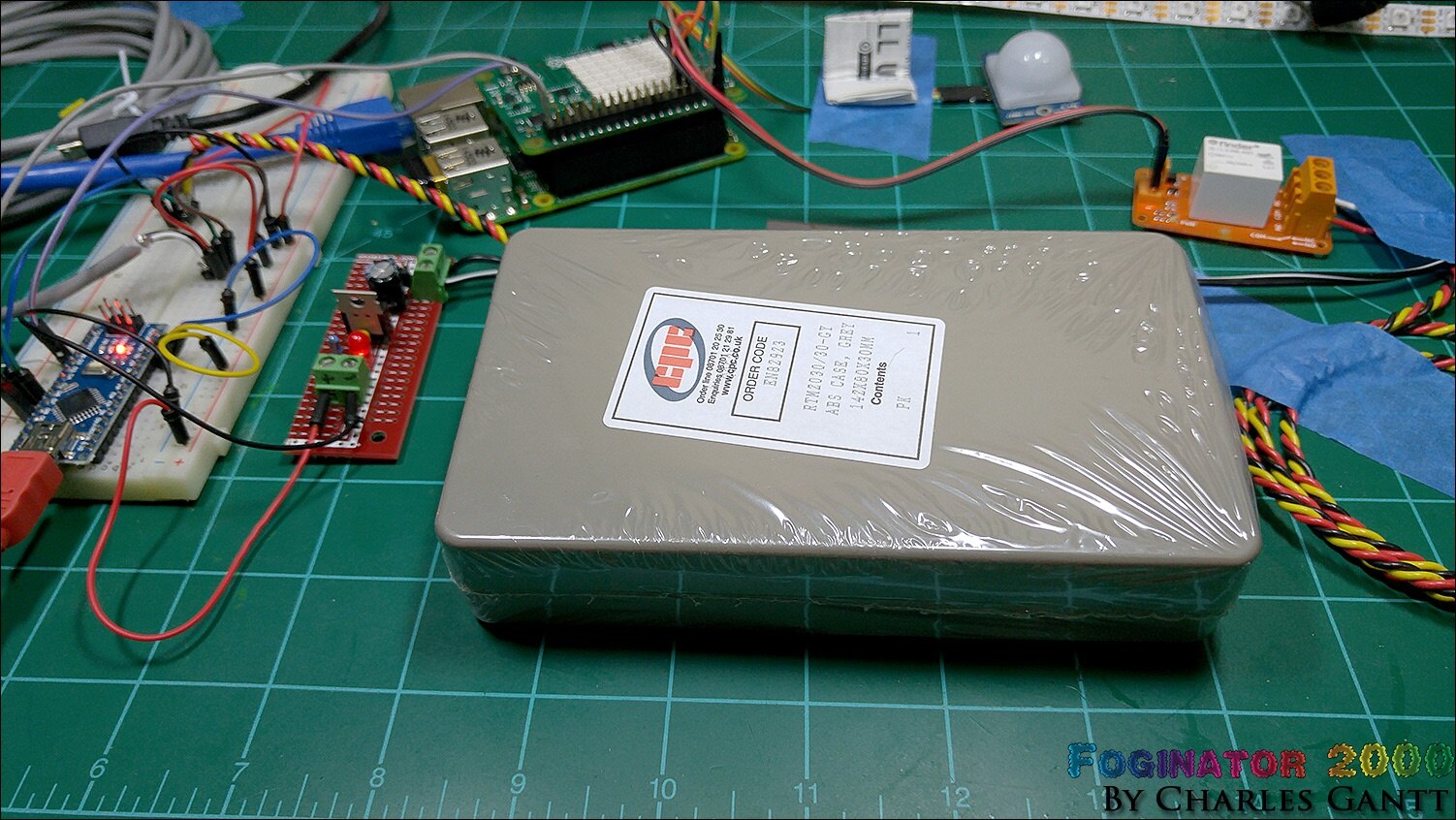
The only special parts we are using tonight is a piece of prototyping board, and a project enclosure. You will need something to cut holes into the project box. I used a dremel multitool with a cutoff wheel, drill bits, and some hand files to accomplish this. You will also need a hot glue gun, to secure the PCBs and the motion sensor.
MCM Part No. | Notes | Qty | Manufacturer / Description |
Prototyping Board | 1 | Circuit Board - 750 Holes | |
Project Enclosure | 1 | ABS Case Gray - 5-5/8" x 3-1/8" x 1-3/16"
|
The Build
To get started let’s look at how the project box is laid out internally. Idealy, a 5” thick box would be used so that the Raspberry PI and Sense Hat could be placed in the enclosure as well. Unfortunately I was unable to find one large enough at Newark or MCM Electronics. So we are going to use this enclosure that is just large enough to house the rest of the electronics.
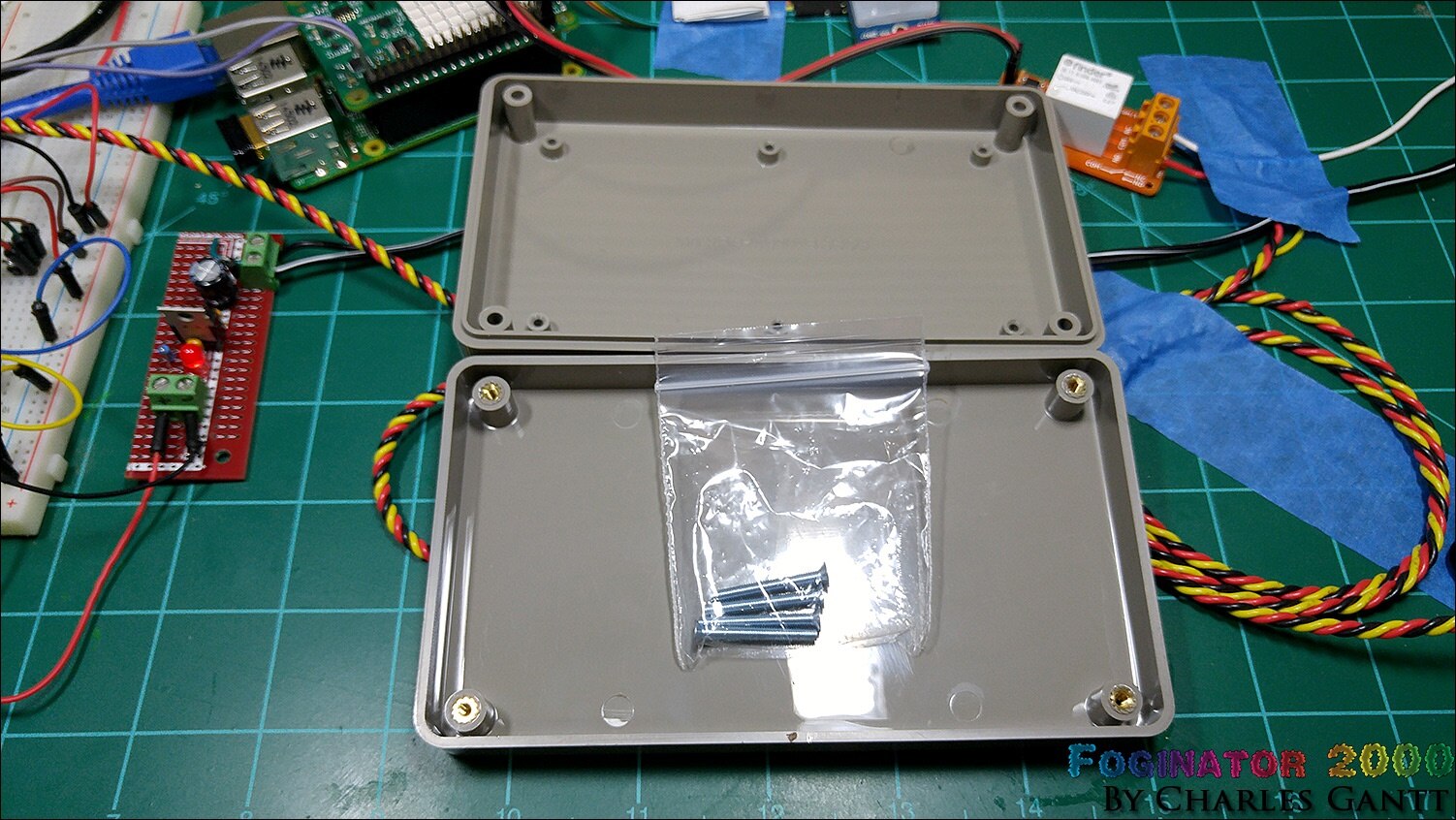
The inside of the project enclosure has several standoffs on one side, and just the enclosures screw standoffs on the other. I am going to use the clean side as the bottom of the box since none of my boards will align with the mounting standoffs on the other side.
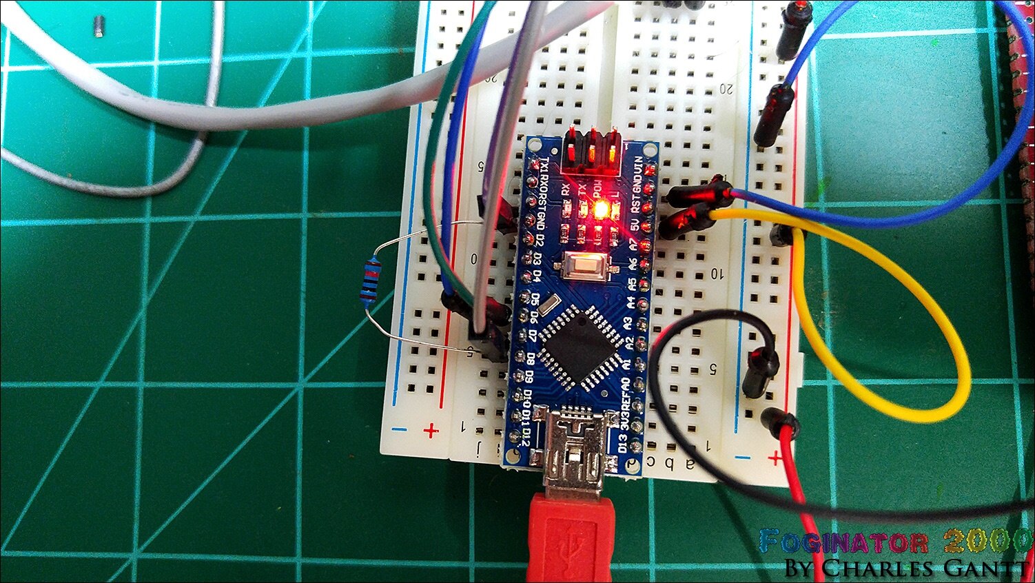
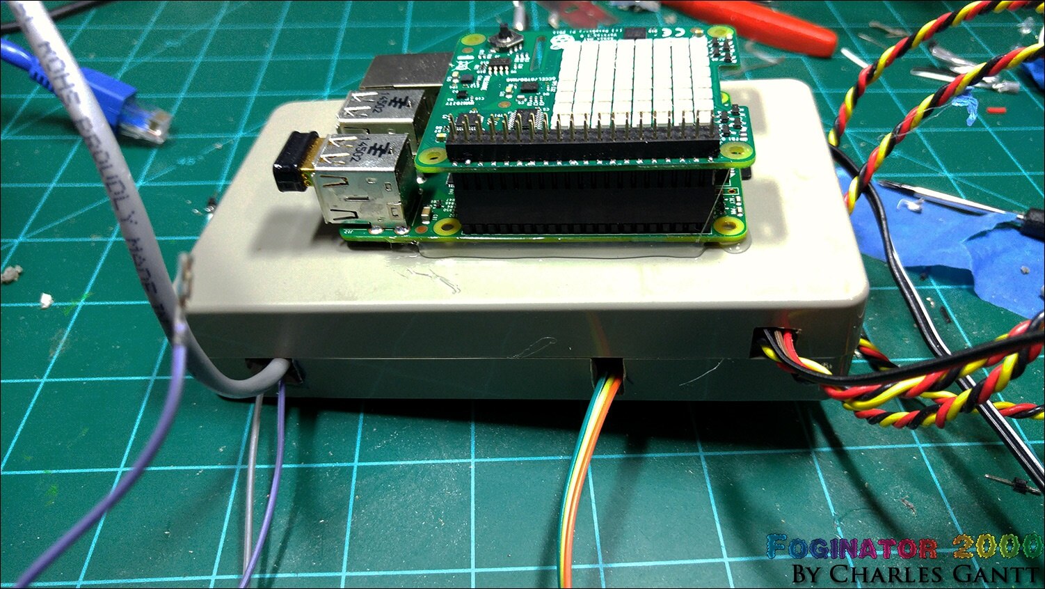
This is the main portion of what we need to move to a prototyping PCB. The Arduino Nano, a pulldown resistor, and the LED cable connections.
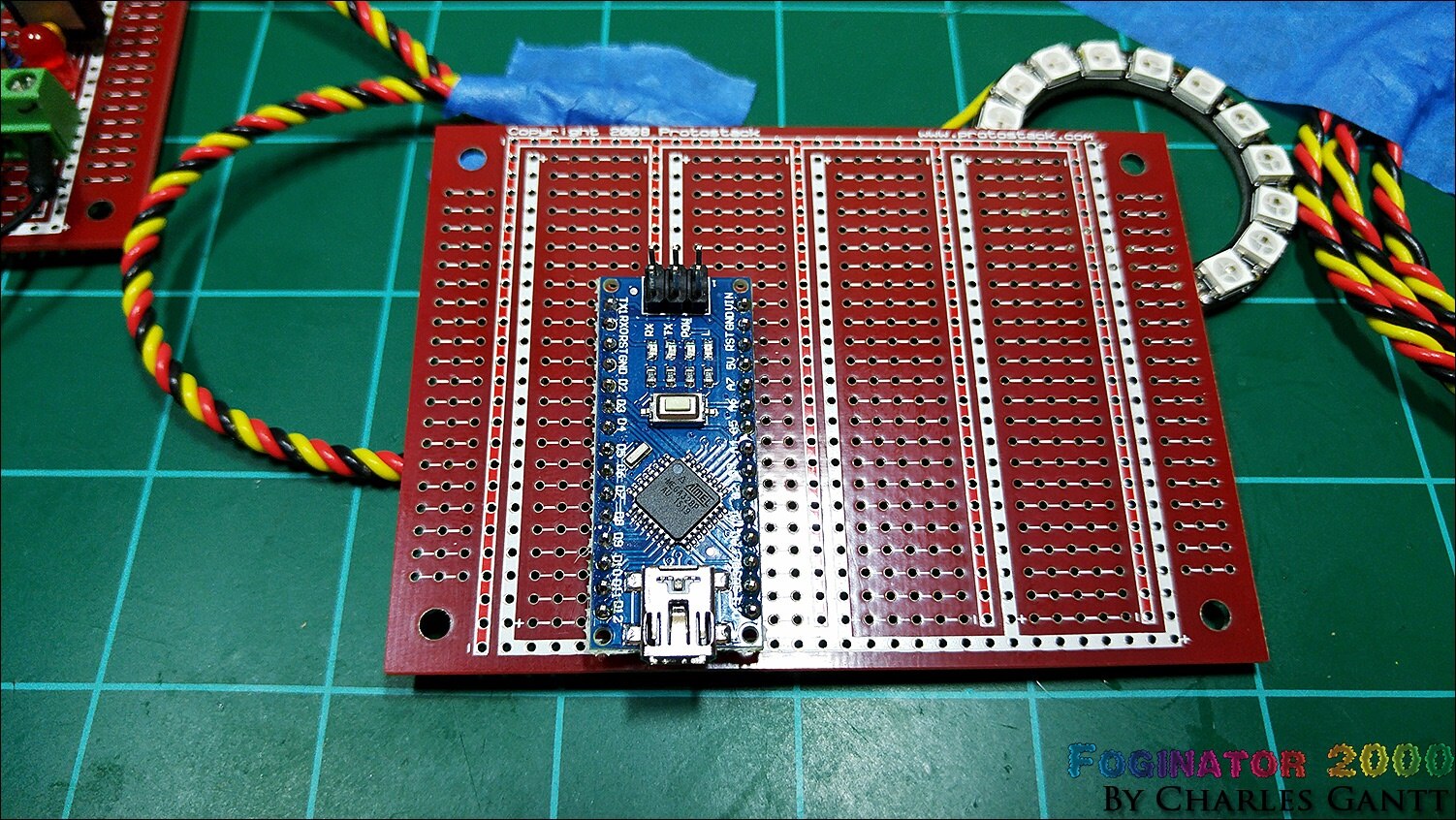
I am again using a Protostack protoboard as I have several laying around. You can use any prototyping board you would like though. I chose to only solder the pins that I was using as well as the 5V and GND pins.
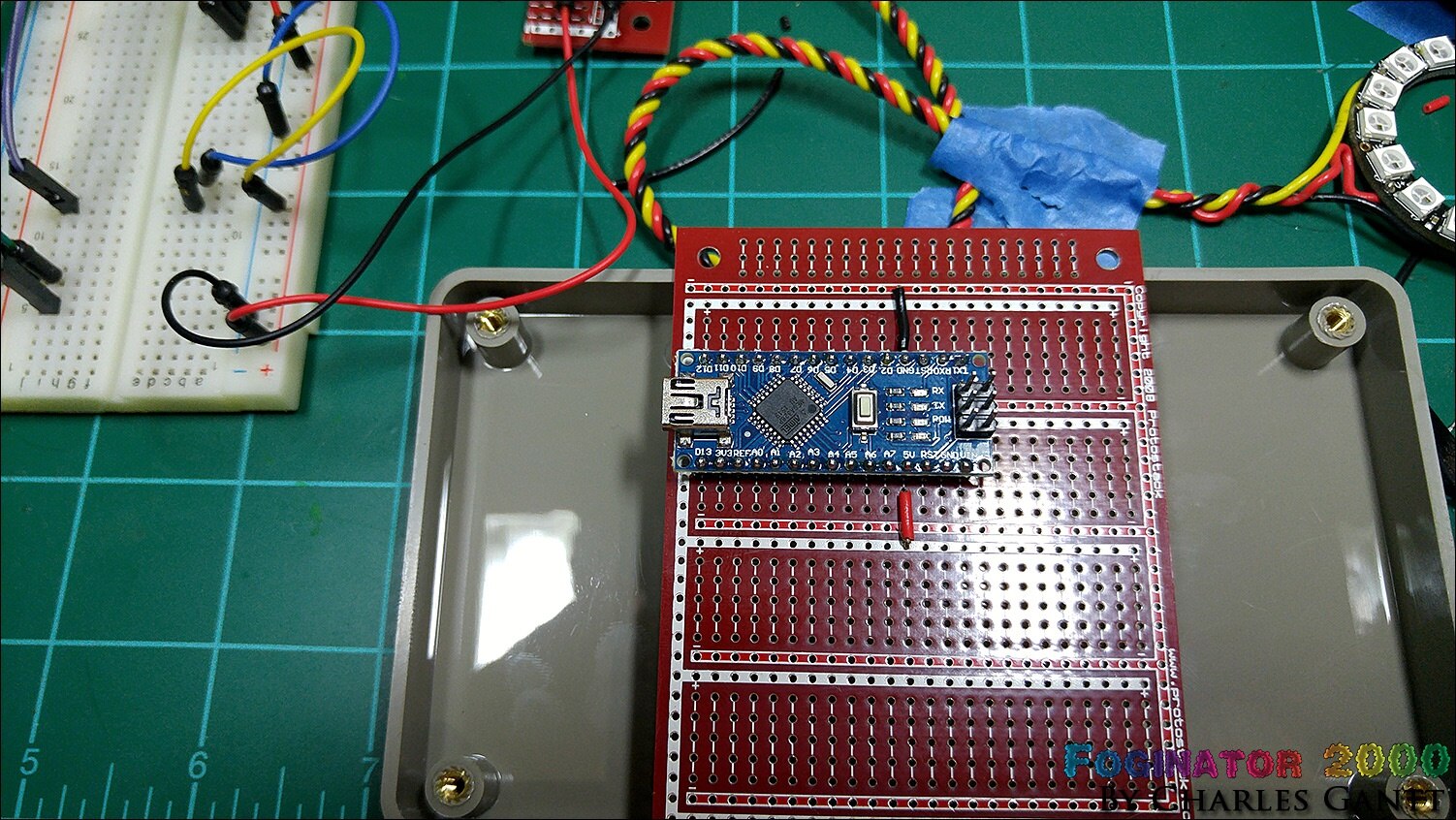
Here you can see that I used jumper wires to connect the GND and 5V lines on the Arduino Nano to the GND and VCC rails on the prototyping board. That is why I love these little boards from Prototstack. They are laid out like a breadboard, with five of the holes connected, and the power rails encircling everything.
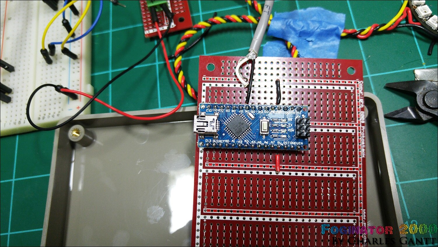
With the power connections made, I soldered in the Neopixel strip. I am not a fan of the microphone cable I used for the connection when soldering to these boards. Their holes are designed for smaller through hole pins, but with a little finesse it fits well. You will notice that I did not solder in the Neopixel ring. I think I killed it on accident, as I could not get it to light up at all.
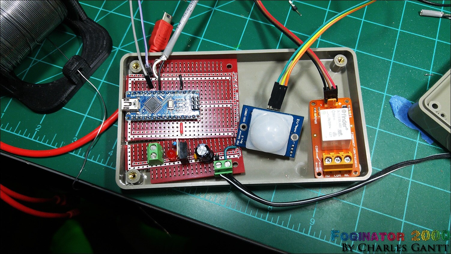
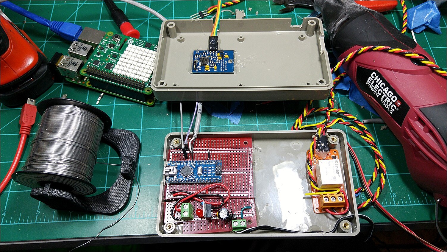
Here you can see the basic layout . Notice I notched both the Arduino protoboard and the 5V power supply board. I forgot to take pics of this process, but I used a hacksaw blade to cut them. A dremel would work too but it produces a lot of glass fiber dust that is very bad to breath. The relay sits on the right, and the PIR sensor will be placed in the top cover through a hole.
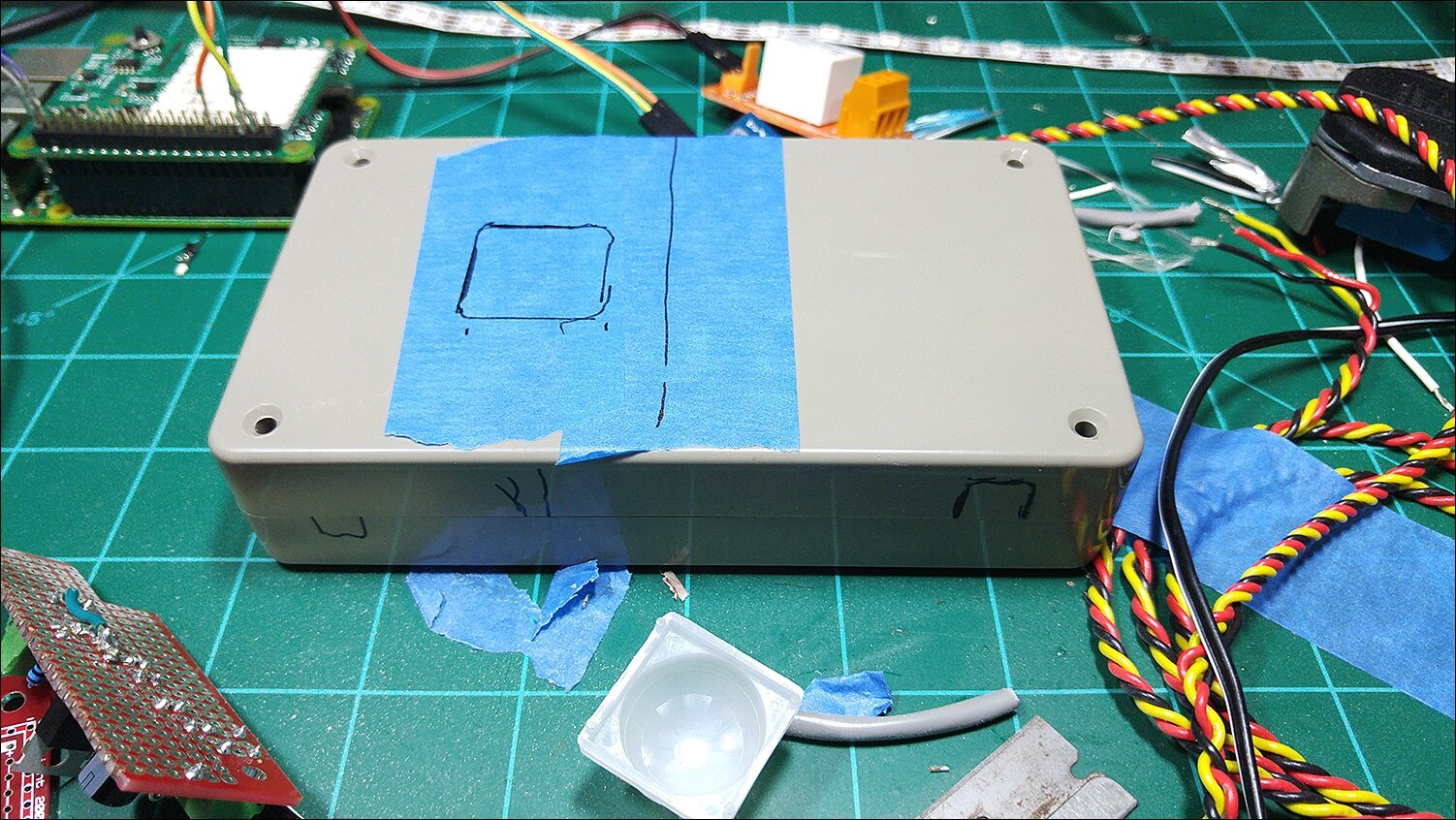
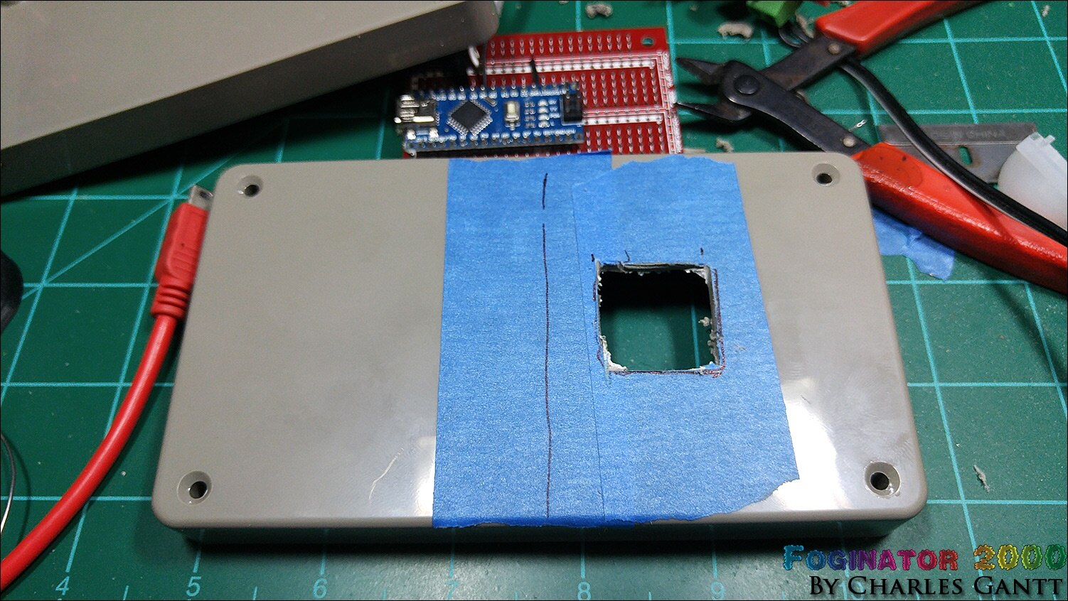
This enclosure needs several holes for the wiring to exit. Here you can see some of them laid out. I used a dremel tool, a drill and drill bit, and some hand files to create and clean up these holes.

Here’s the hole roughed out for the PIR sensor. It is important to get the sensor mounting flush with the top of the case for space concerns inside.
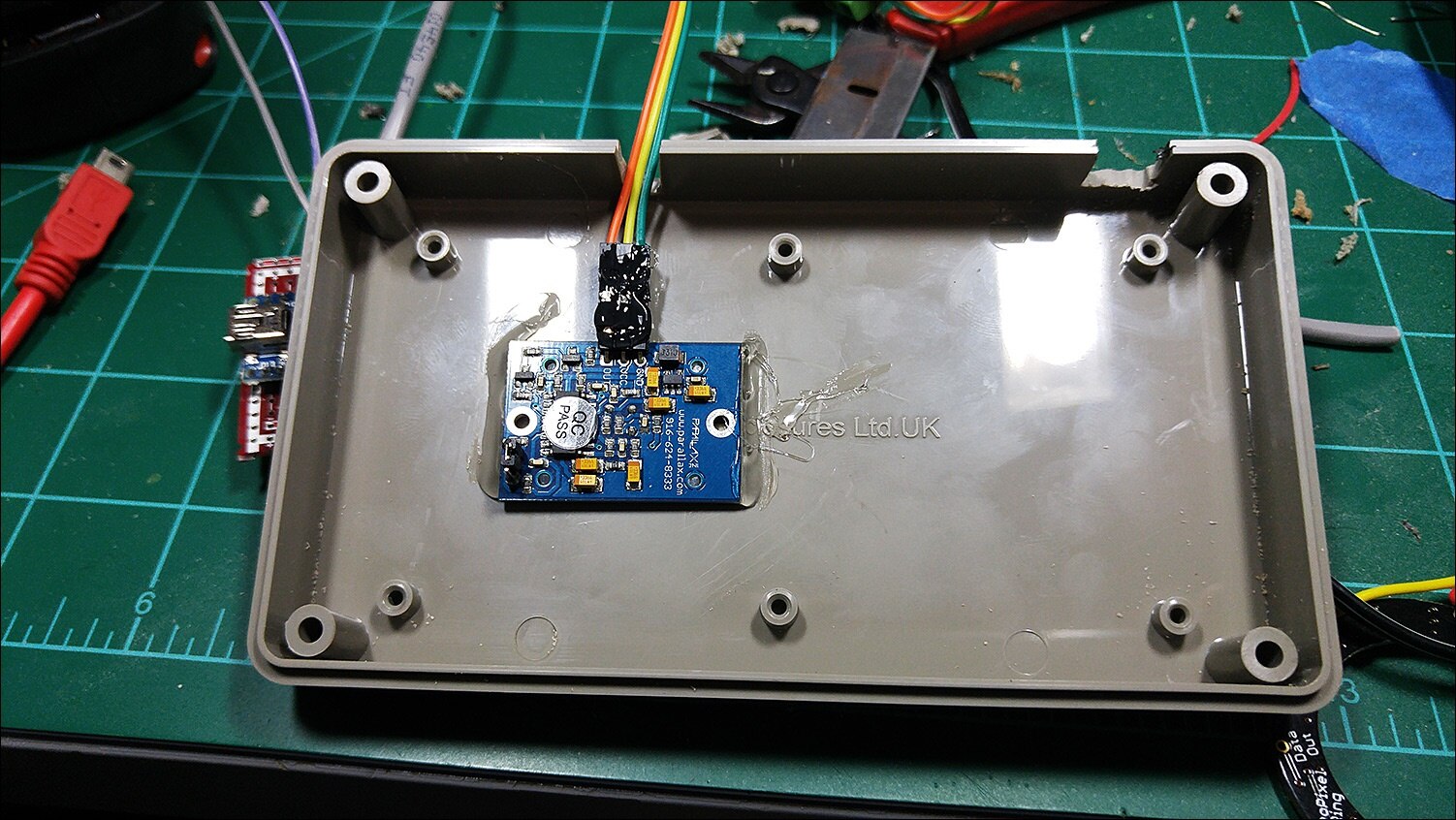
Once everything is fitting nice and tight, I used hot glue to secure the PIR sensor to the case. Note that I hot glued the jumper wires to the pins as well. This prevents them from pulling loose later.
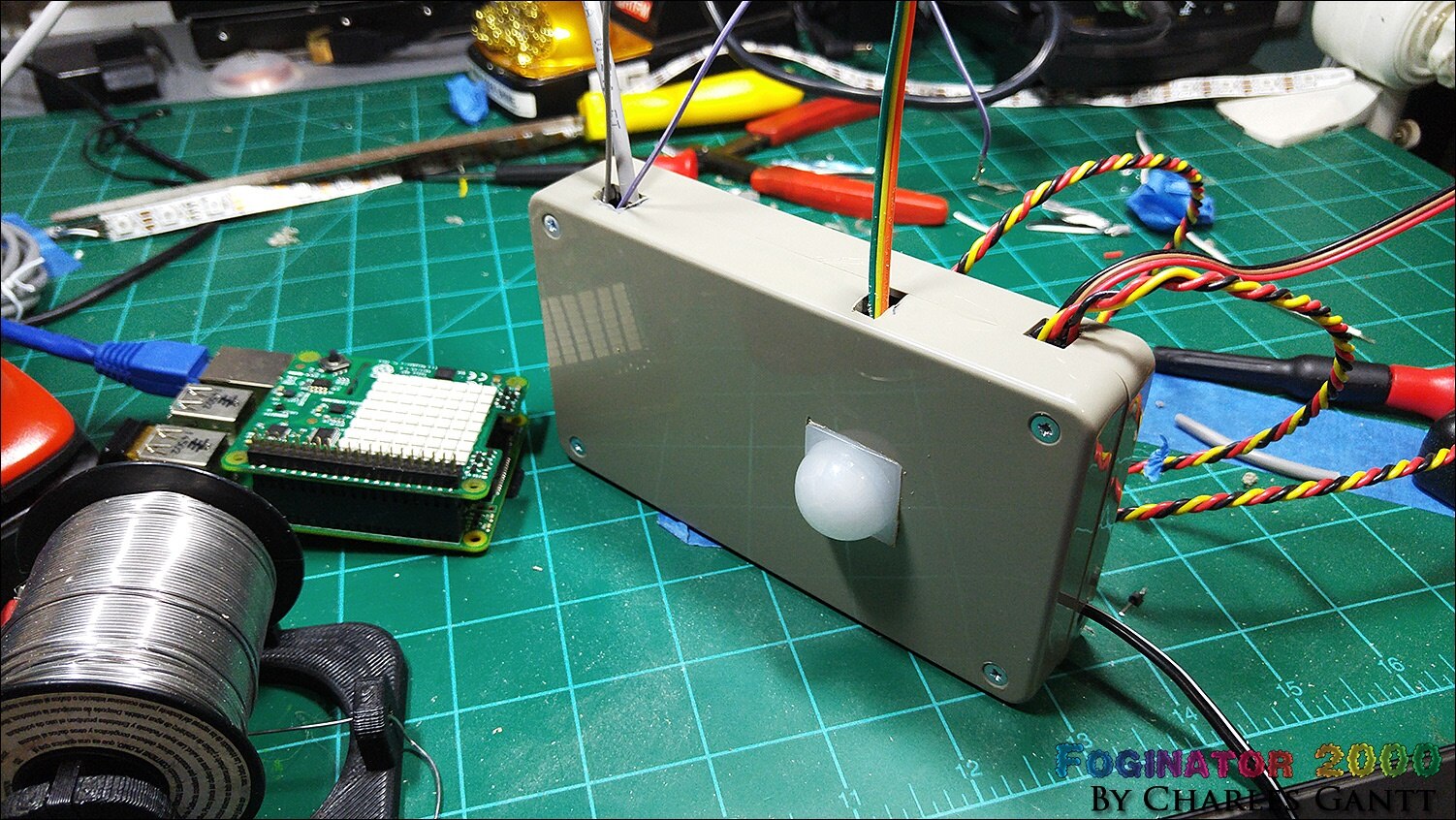
Here you can see everything glued into place, and the power wire ran to the power supply. Not pictured is the dobs of glue that I used to hold all the wires that exit the case in place.
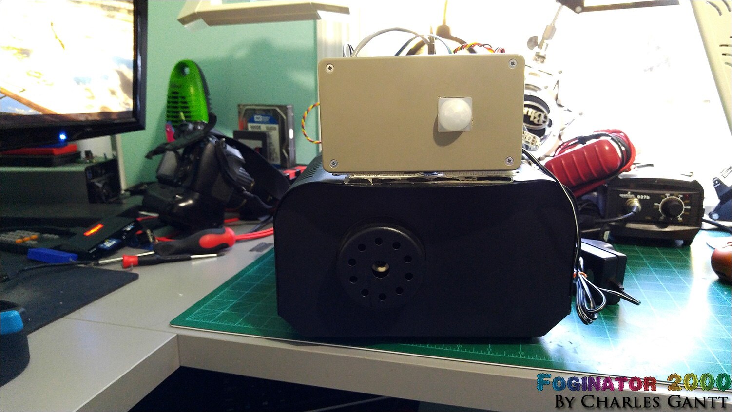
While it is not the most discrete motion sensing project enclosure ever made, it sure does look good once everything is closed up nice and tight.
Thinking ahead in case I ever wanted to reprogram the Arduino, I cut a slot that would allow me to plug in a USB cable. I made the slot oversize as the USB cables I like to keep handy, have a bit of a thicker encasement around the tip.

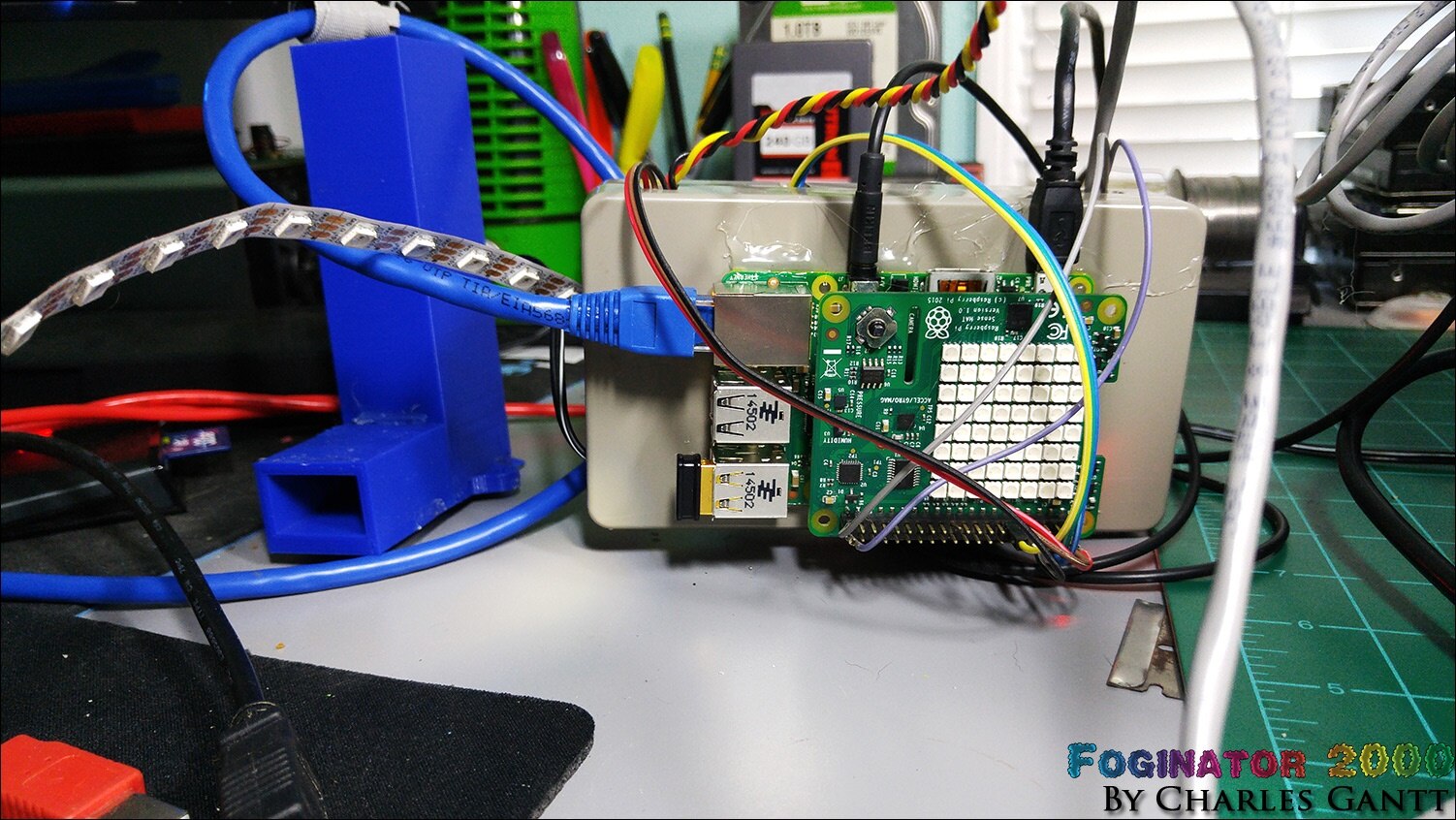
Unfortunately I was unable to fit the Raspberry Pi and Sense Hat inside this project enclosure as I had planned. I needed to keep the stack close to the peripheral boards, so I simply hot glued it to the back of the enclosure.
And a final shot of everything connected and ready to go! Note that the Raspberry Pi has been reoriented in this image. I forgot about the audio cable, and the original way I mounted it would not allow for it to be plugged in and the enclosure still be able to sit upright.
Due to a lack of time, I simply chose to mount the project enclosure on top of the fog machine using some velcro and hot glue. While this is not ideal, it does work quite well.
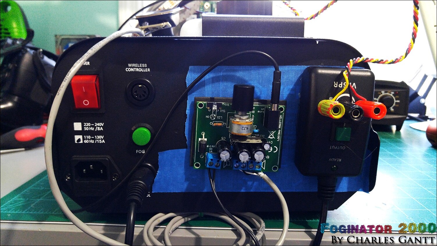
Looking at it from the back, you can see how starved for space this project is. Note the speaker. I found that for small things, blue tape on the fog machine’s surface helps hold the hot glue better.
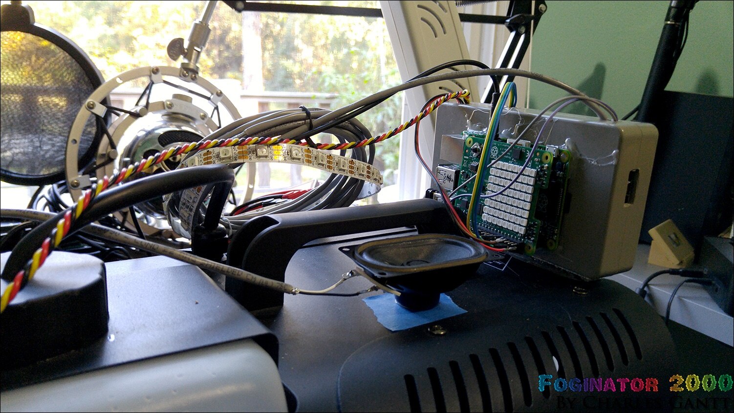
Looking at the back you can see how I mounted the audio amplifier and the fog machine remote switch. Again, blue tape came in handy here to help the hot glue stick better.
The Final Code
I have merged all of the code together and added in some print lines that help troubleshooting any issues. To record the data, you will need to sign up for an Initial State account, and then generate a new API key for your account. You can download this code from its Github Repository which can be found here.
__author__ = 'Charles Gantt'
# This code is part of the Foginator 2000 project developed for the Halloween15 Raspberry Pi Project event at Element14.com and can be found at http://bit.ly/foginator2000


import RPi.GPIO as GPIO
import time
import sys
from sense_hat import SenseHat
from ISStreamer.Streamer import Streamer


logger = Streamer(bucket_name="Foginator2000_Data_10/23/2015", access_key="zLahwAUqKbNKv6YvuT5JuO58EiUOavDa")


sense = SenseHat()
sense.clear()
sensing = True
fog_Armed = True


GPIO.setwarnings(False)
GPIO.setmode(GPIO.BCM)
GPIO.setup(4, GPIO.OUT)
GPIO.setup(17, GPIO.IN)
GPIO.setup(21, GPIO.OUT)


O = (0, 255, 0) # Green
X = (0, 0, 0) # Black


creeper_pixels = [
    O, O, O, O, O, O, O, O,
    O, O, O, O, O, O, O, O,
    O, X, X, O, O, X, X, O,
    O, X, X, O, O, X, X, O,
    O, O, O, X, X, O, O, O,
    O, O, X, X, X, X, O, O,
    O, O, X, X, X, X, O, O,
    O, O, X, O, O, X, O, O
]


black_pixels = [
    X, X, X, X, X, X, X, X,
    X, X, X, X, X, X, X, X,
    X, X, X, X, X, X, X, X,
    X, X, X, X, X, X, X, X,
    X, X, X, X, X, X, X, X,
    X, X, X, X, X, X, X, X,
    X, X, X, X, X, X, X, X,
    X, X, X, X, X, X, X, X
]


var = 0


def is_integration():
  while sensing == True:
        print "IS Start"
        temp = sense.get_temperature()
        temp = round(temp, 1)
        logger.log("Teperature C",temp)
        print "T1"
        humidity = sense.get_humidity()
        humidity = round(humidity, 1)
        logger.log("Humidity :",humidity)
        print "H1"
        pressure = sense.get_pressure()
        pressure = round(pressure, 1)
        logger.log("Pressure:",pressure)
        print "P1"
        logger.log("Trick Or Treat Event #",var)
        print "ToT Event Logged"
        sense.set_pixels(creeper_pixels)
        time.sleep(2)
        sense.set_pixels(black_pixels)
        sense.clear()
        print "IS Done"
        break


def fire_fog():
    while fog_Armed == True:
        print "Trick or Treat Event Sensed"
        print "Lights Start"
        GPIO.output(21,True)
        time.sleep(2)
        print "Relay Triggered"
        GPIO.output(4,True)
        time.sleep(10)
        print "Relay Disabled"
        GPIO.output(4,False)
        time.sleep(20)
        print "Lights Disabled"
        GPIO.output(21,False)
        is_integration()
        print "Trick or Treat Event Finished"
        time.sleep(10)
        print "Watching For Motion"
        break


while True:
    time.sleep(3)
    if GPIO.input(17)==True:
        var = var +1
        print ("var =", var)
        print "Motion Detected"
        fire_fog()
This code has been modified to run continuously while always looking for a motion trigger. To make this code run when you plug the Raspberry Pi in, you will need to set the python script to run on startup via the cron tab.
The Data
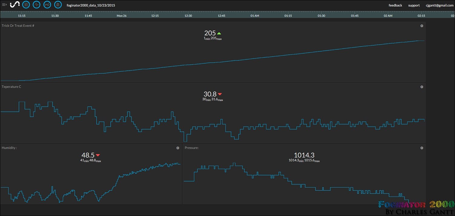
To recap, we are using the Sense Hat to record a few environmental data points including air temperature, humidity and air pressure. The Raspberry Pi then pushes that data to a remote server at Initial State, which then processes it, and displays it in nice graphs, and other visualizations. I have also added a fourth metric called “Trick or Treat Event” that simply increments by one every time a motion event is detected. As you can see in the image below, everything seems to be working perfectly. You can check out the full stream here.
In the video below, you can see me walking into the room, and the sensor tripping when the fog fires. If I have some free time on Halloween before the Trick or Treaters arrive, I am going to add in another meter or so of Neopixel strips to increase the illumination.
That is going to wrap up this installment. I will be back in just a few days with a complete wrap up of this whole project and the results from Halloween night!


